Series capacitor

Status
Not open for further replies.

Jpflex

Electrician big leagues
Location
Victorville
Occupation
Electrician commercial and residential
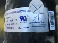
On a fan motor for “mr heater” Industrial 175,000 btu heater there is a wiring diagram.

On the diagram as shown I was just curious on your thoughts on its purpose. Normally they are used as start capacitors to place a phase difference between field poles, however this diagram doesn’t seem to depict this?

Other purposes could be signal filtering, power factor correction for economy. What are other thoughts?

Also how would you think thermostat Bulb and controls work? In the old school days mercury would rise in sensing bulb to close a switch when heat rose.

Do they now use a reastat or variable resistor changing values and voltage drop to Module to sense ambient temp?
 

Attachments

  • F1B1EA21-770F-4463-9F45-845507B3EF06.jpeg
    F1B1EA21-770F-4463-9F45-845507B3EF06.jpeg
    30 KB · Views: 31

Jpflex

Electrician big leagues
Location
Victorville
Occupation
Electrician commercial and residential
Diagram 3
 

Attachments

  • 3C7A79F3-E82A-467F-8B13-627C4C4682B6.jpeg
    3C7A79F3-E82A-467F-8B13-627C4C4682B6.jpeg
    26.2 KB · Views: 13

cadpoint

Senior Member
Location
Durham, NC
My Father always said to go to the Road map!

So in a search for wiring Diagram Mr Heater one gets this (note it does listed as a 170,000 BTU - but bear with me)
https://www.allpartsinc.com/pub/media/attachments/products/MHU_OM_2017.pdf
page 13, first is the wiring diagram, below that is the ladder diagram.

So in the wire diagram at the bottom is B3 motor and note that it states 75 and 80 use a capacitor. Is that your unit I don't know.
Note that B3 is wired direct to ACC and white, now drop to ladder your little diagram doesn't show up.

So I'll assume (a big thing to do here) is that it's part of the motor only by design but not presented in the Road maps...

A Story:
Just about all AC motors have a capacitor to make help make it spin and fire when the motor sees the negative part of sign wave.
Household wise, most appliances are short term usages and lower size motors so it doesn't need to never stop firing.
An industrial floor buffer when started is about the only thing one can hear something turn off and that works on about this
OP same principle question.

I can't see the diagram clear enough to determine exactly what that is!

Let's think about that wire diagram on the motor the first resistor is in parallel with the capacitor, So it's also turning on and off
in seeing the sine wave also. But due to duration of heating aspect it's on and off a lot, thus the second resistor or rheostat which
will also be worked with the fail safe of whatever the device is off to the right side. Be it a thermo release of some sorts.
The Capacitor never stops firing it calms down because the other resistor or rheostat elements have come up heat and calmed it down.

Do they now use a rheostat or variable resistor changing values and voltage drop to Module to sense ambient temp?
So to answer your question, yes (I'll Assume)
 

synchro

Senior Member
Location
Chicago, IL
Occupation
EE
The motor schematic appears to show that it's a "permanent split capacitor" type. The series capacitor provides a phase shift just like in a capacitor start motor, but the capacitor is small enough that it can remain connected. It doesn't have the starting torque of a capacitor start, but it's sufficient for many applications such as blowers.
 
Have to disagree (replying to cadpoint)-
3-phase motors don't need cap's at all.
Only a few types of single-phase motors need them to run, and only some for starting. It's all about creating a rotating magnetic field so the armature doesn't just vibrate.

And what is this "turn-on/turn-off" stuff? Neither capacitors nor resistors behave that way.
 

cadpoint

Senior Member
Location
Durham, NC
Have to disagree (replying to cadpoint)-
3-phase motors don't need cap's at all.
Only a few types of single-phase motors need them to run, and only some for starting. It's all about creating a rotating magnetic field so the armature doesn't just vibrate.

And what is this "turn-on/turn-off" stuff? Neither capacitors nor resistors behave that way.
the link only shows a line L1 and A line for Neutral The OP didn't state the exact circuit size of what the exact device was.

Anything connected to a live wire is never off granted, so you are correct. A Capacitor fires on the down side of the sine wave,
and recharges on the positive.

AC is Still pulsing on and off through a sine, So you want to argue about that OK!

How that power is used by the individual elements of an electronic circuit varies.
Besides all that most Electronic Devices change to DC as the first thing in a wire diagram thus no need for a capacitor,
this was also not the case in the link.
 

Jpflex

Electrician big leagues
Location
Victorville
Occupation
Electrician commercial and residential
I used a capacitive / inductive clamp to scope the igniter secondary wire for constant spark.

The image was not like I’ve seen in automotive coil output. The voltage spike averaged under 10k volts with not much visual firing line voltage besides a lot of coil oscillating voltage. A constant repeating blue spark was present in the flame. I did clean the electrode gap but didn’t suspect much problem with ignition system in regards to the system misfiring or pulsing fire.

I ruled this out to faulty fuel injector spray pattern or fuel volume in general.

Besides that does anyone know how the igniter coil system works? Cars require a bit of charge time for coil to saturate before firing and use a transistor to interrupt primary current. This is why they went to COP one coil per spark plug cylinder or more saturation time available.

However this heater does not have this, so how can it develop saturation so fast and deliver spark to what appears almost constant?

Would you think the primary coil would shunt or contact secondary as a boost transformer or would secondary be more likely isolated from primary coil as purely inductive?
 

synchro

Senior Member
Location
Chicago, IL
Occupation
EE
I used a capacitive / inductive clamp to scope the igniter secondary wire for constant spark.

The image was not like I’ve seen in automotive coil output. The voltage spike averaged under 10k volts with not much visual firing line voltage besides a lot of coil oscillating voltage. ...

Besides that does anyone know how the igniter coil system works? Cars require a bit of charge time for coil to saturate before firing and use a transistor to interrupt primary current. This is why they went to COP one coil per spark plug cylinder or more saturation time available.

However this heater does not have this, so how can it develop saturation so fast and deliver spark to what appears almost constant?

It might have a capacitive discharge ignition (CDI) system where energy is stored in a capacitor instead of an inductance (as it is with an ignition coil typically used in cars).

In an automotive ignition coil, 12V is applied across the primary winding which then causes the current to ramp up and build a magnetic field within the core. And given enough time the core can reach saturation. In the old days when points were used, a series resistor was used after the engine was started to limit the current when in saturation. Electronic ignitions limit the duration of the coil charging period so that it doesn't go into saturation and continue to draw current, and so a series resistor to limit the current is not necessary.

In the picture at the link below, when capacitor C1 is being charged up, diode D1 is forward biased with only about 0.7V across it (and therefore across the coil primary). Therefore you will see very little voltage on the coil output during this charging period relative to the baseline. After the capacitor is charged up to several hundred volts, the SCR (aka thyristor) Th1 is fired, causing the capacitor to discharge into the ignition coil. The repetition rate of the sparks is typically limited by how fast you can charge the capacitor, and not by the coil which is acting only as a transformer and not for storing energy.


25709519f26ad120bd186cb8a5ce1e2d.jpg
 
Last edited:
The words are important (and the OP was asking about a motor, not an ignition system)-

A Capacitor fires on the down side of the sine wave, and recharges on the positive.
We usually say that a capacitor "discharges", not "fires"; how fast is entirely dependant on its own and the circuit's impedances.

AC is Still pulsing on and off through a sine, So you want to argue about that OK!
I also find it hard to describe a sine wave as "pulsing". If you want to, that's OK, but at best that's misleading since we usually talk about the half-cycles.
 

Jraef

Moderator, OTD
Staff member
Location
San Francisco Bay Area, CA, USA
Occupation
Electrical Engineer
The motor schematic appears to show that it's a "permanent split capacitor" type. The series capacitor provides a phase shift just like in a capacitor start motor, but the capacitor is small enough that it can remain connected. It doesn't have the starting torque of a capacitor start, but it's sufficient for many applications such as blowers.
Bingo, this is just a very basic PSC motor diagram, the type used on a lot of single phase fan pans pump motors because starting torque of the motor is low, but that’s fine for a centrifugal load like a fan or pump.

Although I have to say that in this case, using only two wire colors (pink and orange) but showing four connections is about as stupid as one can get…
 

Jpflex

Electrician big leagues
Location
Victorville
Occupation
Electrician commercial and residential
It might have a capacitive discharge ignition (CDI) system where energy is stored in a capacitor instead of an inductance (as it is with an ignition coil typically used in cars).

In an automotive ignition coil, 12V is applied across the primary winding which then causes the current to ramp up and build a magnetic field within the core. And given enough time the core can reach saturation. In the old days when points were used, a series resistor was used after the engine was started to limit the current when in saturation. Electronic ignitions limit the duration of the coil charging period so that it doesn't go into saturation and continue to draw current, and so a series resistor to limit the current is not necessary.

In the picture at the link below, when capacitor C1 is being charged up, diode D1 is forward biased with only about 0.7V across it (and therefore across the coil primary). Therefore you will see very little voltage on the coil output during this charging period relative to the baseline. After the capacitor is charged up to several hundred volts, the SCR (aka thyristor) Th1 is fired, causing the capacitor to discharge into the ignition coil. The repetition rate of the sparks is typically limited by how fast you can charge the capacitor, and not by the coil which is acting only as a transformer and not for storing energy.


25709519f26ad120bd186cb8a5ce1e2d.jpg

However based on the diagram since a diode blocks current flow in the direction of the arrow then there seems to be a short circuit path from negative ground through first what appears to be a type of zener diode? TH1 traveling to D1 To source 387.5 volt (positive if dc or ac alteration)

How is this not a problem? First diode must not be allowing current starting from chassis to second diode mentioned ?
 

synchro

Senior Member
Location
Chicago, IL
Occupation
EE
I provided a link to this schematic of a CDI type ignition in a motor scooter because it illustrates how a CDI is implemented.
The diode D2 rectifies the AC waveform coming from a magneto and this charges capacitor C1 with a positive voltage on its left side relative to circuit ground (in this case to a maximum of 387.5 VDC) . The charging current flows through D2 into C1, and then from C1 through the parallel combination of diode D1 and the coil primary, and into the circuit ground. In this application a voltage from a pickup coil triggers Silicon Controlled Rectifier (SCR, aka thyristor) Th1, which when it's fired will pull the left side of a fully charged capacitor C1 to ground. That will cause a negative 387.5V to be applied across the primary of the spark coil (Zundspule in German :) ). The turns ratio of the ignition coil will boost this up to the several thousand volts necessary for spark ignition.
 

Jpflex

Electrician big leagues
Location
Victorville
Occupation
Electrician commercial and residential
I provided a link to this schematic of a CDI type ignition in a motor scooter because it illustrates how a CDI is implemented.
The diode D2 rectifies the AC waveform coming from a magneto and this charges capacitor C1 with a positive voltage on its left side relative to circuit ground (in this case to a maximum of 387.5 VDC) . The charging current flows through D2 into C1, and then from C1 through the parallel combination of diode D1 and the coil primary, and into the circuit ground. In this application a voltage from a pickup coil triggers Silicon Controlled Rectifier (SCR, aka thyristor) Th1, which when it's fired will pull the left side of a fully charged capacitor C1 to ground. That will cause a negative 387.5V to be applied across the primary of the spark coil (Zundspule in German :) ). The turns ratio of the ignition coil will boost this up to the several thousand volts necessary for spark ignition.

This is my point, if the left side of capacitor c1 charges positive and is being pulled down to ground at any point through either Th1 or D1 diode WITHOUT A LOAD before ground then you have a short condition nothing to limit current flow
 

synchro

Senior Member
Location
Chicago, IL
Occupation
EE
This is my point, if the left side of capacitor c1 charges positive and is being pulled down to ground at any point through either Th1 or D1 diode WITHOUT A LOAD before ground then you have a short condition nothing to limit current flow

What provides the AC voltage on the left of the schematic is not shown. It's possible that the magneto powered by the flywheel does not provide any significant voltage at the time when the SCR is triggered to create a spark. Also, the magneto may have a significant output reactance that limits how fast the current can increase even when the magneto is shorted. And so if the SCR is only conducting during a small time interval, the current from the magneto will be limited even if its output is shorted during that interval.

For the ignition in a heater like you posted, the charging circuit for the capacitor could be synchronized so that it's disconnected before the SCR is fired. Or it might just be firing close to the zero crossings of the 60Hz voltage waveform.
 
Last edited:

JoeStillman

Senior Member
Location
West Chester, PA
Google "Permanent Split Capacitor Motor". You'll find this exact diagram, but without the two extra pink wires. My guess is that they show you those so you don't have to wonder what the two extra wire nuts in the terminal box are for.
 

kwired

Electron manager
Location
NE Nebraska
PSC motor is sort of same thing as capacitor start capacitor run capacitor except it has no start capacitor. As mentioned they are common on fans and pumps that don't need higher starting torque as well as other lower torque applications.

Until they started with the ECM and other higher efficiency methods on HVAC majority of single phase motors in that industry were nearly all PSC type motors. Some compressors needed a start capacitor because of higher starting torque needed but many were just a PSC motor.
 
Status
Not open for further replies.
Top