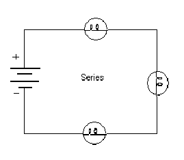
Series Circuit example

Status
Not open for further replies.
I have Basic Electrical Theory 3rd edition by Mike Holt. In the parallel series examples, it shows a conduit with going to 3 boxes, with receptacles in each box pigtailed off each other as an example of a parallel circuit. It can be found on page 136 if anyone has this. This is an easy concept to grasp as I do it all the time, and instead of a diagram it shows a picture of outlets being pigtailed. Well, on the series circuits all there is diagram , and as I'm not too familar with motor control having a hard time relating. Can anyone show me or explain how you would actually wire 3 different outlets in series? Thanks.
 

Dennis Alwon

Moderator
Staff member
Location
Chapel Hill, NC
Occupation
Retired Electrical Contractor
Normally outlets are done in parallel but a series connect would be just like the old xmas lights used to be- if one goes out the connection is lost. Here is an example of lighting in series.

seriescircuit.gif


Here are receptacles in parallel

multiple recet cr.jpg
 
still confused

still confused

Dennis, like I said I understand the outlet diagram in parallel, and the battery diagram in series. Richxtlc , your diagram was a lighting diagram which was al little helpful but my initial question is what would a diagram of outlets in series look like. Or is it possible? Correct me if I'm wrong but from what I gather if you had three boxes with a plug in each you would have the hot conductor going to the hot side, then coming out of the neutral side onto the next hot side of the next box, coming out of the neutral side onto the last plug then a neutral gong back into each box and back to the panel? Now if you were to plug a load in on any of the first two it would only work if something was plugged into the last outlet? Thanks for being patient I'm really trying to understand series circuits.
 

TimK

Member
Location
Tacoma, WA
Dennis, like I said I understand the outlet diagram in parallel, and the battery diagram in series. Richxtlc , your diagram was a lighting diagram which was al little helpful but my initial question is what would a diagram of outlets in series look like. Or is it possible? Correct me if I'm wrong but from what I gather if you had three boxes with a plug in each you would have the hot conductor going to the hot side, then coming out of the neutral side onto the next hot side of the next box, coming out of the neutral side onto the last plug then a neutral gong back into each box and back to the panel? Now if you were to plug a load in on any of the first two it would only work if something was plugged into the last outlet? Thanks for being patient I'm really trying to understand series circuits.

Yes you will need some kind of load in each outlet to complete the circuit. But just so you can get this in your head, take 3 keyless lamp holders, yep the kind you put in garage and unfinished basements, and wire them up in series, look at them, then wire them up in parallel and see what the difference is in brightness. You will also be able to take readings right on the back side of the fixture.
 

Dennis Alwon

Moderator
Staff member
Location
Chapel Hill, NC
Occupation
Retired Electrical Contractor
Richxtlc , your diagram was a lighting diagram which was al little helpful but my initial question is what would a diagram of outlets in series look like.
Richxtlc' diagram could be receptacles and would be wired the same. They would not work as such sinch something would need to be installed in each receptacle.

BTW, an outlet can be a lighting outlet or a receptacle so be specific.
 

Dennis Alwon

Moderator
Staff member
Location
Chapel Hill, NC
Occupation
Retired Electrical Contractor
Correct me if I'm wrong but from what I gather if you had three boxes with a plug in each you would have the hot conductor going to the hot side, then coming out of the neutral side onto the next hot side of the next box, coming out of the neutral side onto the last plug then a neutral gong back into each box and back to the panel? Now if you were to plug a load in on any of the first two it would only work if something was plugged into the last outlet? Thanks for being patient I'm really trying to understand series circuits.

You got it but remember you would not have enough power at each outlet to run 120V equipment. Their is a lot of resistance that you go thru to get to the next outlet.
 
Thanks

Thanks

Thanks everyone that helps clear things up a bit. I especially appreciate the comment on resistance, as that is basically why no outlets are wired like that since you would not have 120V at the end of the line, and another good point to be specific on a plug could be a lighting outlet.
 

charlie b

Moderator
Staff member
Location
Lockport, IL
Occupation
Semi-Retired Electrical Engineer
. . . that is basically why no outlets are wired like that since you would not have 120V at the end of the line. . . .
It is not just that the outlet at the end of the line would be low on voltage. Just to clarify (or confuse) the matter, if you had three receptacle outlets wired in series, and if you had identical loads plugged into all three, then the 120 volts from the source would be split evenly across the three loads. That is, each load would have only 40 volts.
. . . .and another good point to be specific on a plug could be a lighting outlet.
Yes, a receptacle outlet is allowed to serve in place of the lighting outlet that many rooms are required to have. But again to be clear about the point Dennis had made, the light fixture in the ceiling is also attached to an ?outlet,? and so is the 120 volt smoke detector, and so is a hard wired baseboard heater. Most people outside the profession would see the word ?outlet? and envision a receptacle. The term means much more than that.
 

kwired

Electron manager
Location
NE Nebraska
I have Basic Electrical Theory 3rd edition by Mike Holt. In the parallel series examples, it shows a conduit with going to 3 boxes, with receptacles in each box pigtailed off each other as an example of a parallel circuit. It can be found on page 136 if anyone has this. This is an easy concept to grasp as I do it all the time, and instead of a diagram it shows a picture of outlets being pigtailed. Well, on the series circuits all there is diagram , and as I'm not too familar with motor control having a hard time relating. Can anyone show me or explain how you would actually wire 3 different outlets in series? Thanks.

I don't know the exact content of the book you mention, but like most books on basic electrical theory, I would think there would be mention of Ohm's law, and Kirchoff's laws. Find those in that book and apply them to the circuit in question to see what is happening in the circuit, and maybe even practice some examples that may be in the book. You hopefully have a low voltage source to do some practice and experimenting with - house voltage is not a good idea to play with, and even less of a good idea when still learning basic theory.
 

TimK

Member
Location
Tacoma, WA
I don't know the exact content of the book you mention, but like most books on basic electrical theory, I would think there would be mention of Ohm's law, and Kirchoff's laws. Find those in that book and apply them to the circuit in question to see what is happening in the circuit, and maybe even practice some examples that may be in the book. You hopefully have a low voltage source to do some practice and experimenting with - house voltage is not a good idea to play with, and even less of a good idea when still learning basic theory.

I thought that just taught you to respect it!:)
 

hbiss

EC, Westchester, New York NEC: 2014
Location
Hawthorne, New York NEC: 2014
Occupation
EC
I think your confusion is because you are thinking about receptacles in series. While it's certainly possible to do, it's not done because there is no use for it and you know that. Think instead of switches in series which is the normal way they are wired.

-Hal
 

mivey

Senior Member
:? And how is that?
In from the previous receptacle, out to the next, meaning the individual conductors are in series (like one continuous length with splices at the receptacles).

The loads are tied between the grounded and ungrounded conductor and thus the "outlets" (and the loads) are in parallel.
 

Dennis Alwon

Moderator
Staff member
Location
Chapel Hill, NC
Occupation
Retired Electrical Contractor
In from the previous receptacle, out to the next, meaning the individual conductors are in series (like one continuous length with splices at the receptacles).

The loads are tied between the grounded and ungrounded conductor and thus the "outlets" (and the loads) are in parallel.

I think calling it series is deceptive.
 

G._S._Ohm

Senior Member
Location
DC area
I think calling it series is deceptive.
You're right.
All the hot terminals are part of a single circuit node and no one would say these tiepoints, junctions, whatever, are in series since they are part of a single node.

If nothing is plugged into the outlets then we have non-connected parallel wires and so there is no circuit.

If only one receptacle is being used then it is a series circuit.
 

mivey

Senior Member
I think calling it series is deceptive.
Not at all. The conductor segments are most definitely in series and we actually consider the circuit series impedance. That is the perfect circuit for making a series voltage drop calculation.

Just a matter of terminology, not a matter of deception.
 

mivey

Senior Member
All the hot terminals are part of a single circuit node and no one would say these tiepoints, junctions, whatever, are in series since they are part of a single node.
They are most certainly not a single node, unless we consider the circuit length to be negligible.
 
Status
Not open for further replies.
Top