Can anyone explain a real life situation or scenario where a series RLC or Parallel RLC circuit exists
A series RLC (a series connection of a resistor, inductor, and capacitor) is used for "traps" to eliminate harmonics of a specific frequency. At the resonant frequency 1/(2π√LC), a series RLC that's placed in shunt across filter input lines (or from line to ground) will present a low impedance and therefore attenuate a harmonic near that frequency.
A parallel resonant RLC circuit can be used for a bandpass filter when placed in shunt across circuit conductors, or a notch filter (aka bandstop filter) when placed in series with a conductor. A parallel resonant circuit will present a high impedance at its resonant frequency.
Both series and parallel resonant circuits can be used in wireless charging.
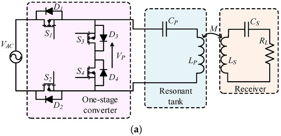
Below is a simple example of a wireless charging circuit with a series resonant "tank" inductively coupled to a series resonant load.
Tesla's ideas for wireless power transfer relied on resonant circuits.
A spark-gap switched Tesla coil has a high impedance secondary RLC resonant circuit magnetically coupled to a primary resonant circuit. The "torus" electrode has a self-capacitance to the surrounding grounded objects. The spark gap completes the primary RLC circuit when the secondary voltage from the mains frequency transformer that's charging the capacitor reaches the breakdown voltage of the gap. Then the energy of 1/2 CV
2 that's stored in the capacitor is exchanged to the primary, and vise-versa as oscillation occurs in the resonant primary circuit. And that oscillating primary current is coupled by mutual inductance to the resonant secondary circuit, which then builds up high voltage oscillations because of its high impedance level (large L/C ratio).
Both the primary and secondary resonant circuits could be appropriately viewed as being parallel resonant. But from the point of view of the spark gap, it sees a series resonant RLC circuit because the L and C are in series with it. And so sometimes you have to be more specific about what exactly you are referring to.

By the way, "L" is used for the symbol of an inductor in honor of Heinrich Lenz:
https://nationalmaglab.org/magnet-a...netism/pioneers/heinrich-friedrich-emil-lenz/")