pvgreeze
Member
- Location
- Philadelphia
- Occupation
- Electrical Engineer
Hello all...I have an unusual predicament that I've run into a couple of times for a couple of perspective projects.
I've run into a number of meter enclosures that feed two separate service disconnects, and the two sets of parallel conductors are tapped within the meter enclosure, so the only available points of interconnection exist outside of the meter enclosure. In one particular instance, there are two separate 200A circuits (3/0 Cu) coming out of the meter enclosure, and we want to interconnect a 225A PV circuit on the line side.
I'm trying to think of different interconnection solutions aside from 1) upgrading one of the existing 200A circuits to 225A and connecting on the line side of the MCB or 2) downsizing the AC output of the system.
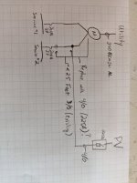
Is it possible to intercept one of the two 200A circuits and interconnect via taps? Sorry if this is a stupid solution, but I can't think of many other options. My thought process was to replace one of the 3/0 feeders leaving the meter enclosure with a 4/0 meter between the load side of the meter and the PV interconnection (we have utility access inside of the meter enclosure). Below the meter, we will install our taps with the existing 3/0 (200A) circuit and our incoming 4/0 (225A). In essence, there will be 4/0 between the meter and the tap, 4/0 between the tap and the PV disconnect (fused for 225A), and 3/0 between the tap and the existing 200A MCB. This scenario seems acceptable under 240.21(B)(2) with the exception of the conductor between the meter and tap not being a 'feeder' but rather a 'service' conductor.
Does any of this sound reasonable? I apologize if what I am describing is is a very rudimentary question or a completely code violation filled way to interconnect. I've attached a sketch to help illustrate what I'm describing. I'm just trying to figure out the best way to interconnect a solar system that is sized off of a single utility meter that has multiple services tapped out of the meter enclosure, and I'm still learning the basics of the solar world. Thanks, -pvgreeze
PS - I read thru that other feeder tap thread, but that seems concerned with load side interconnection, not line side.
I've run into a number of meter enclosures that feed two separate service disconnects, and the two sets of parallel conductors are tapped within the meter enclosure, so the only available points of interconnection exist outside of the meter enclosure. In one particular instance, there are two separate 200A circuits (3/0 Cu) coming out of the meter enclosure, and we want to interconnect a 225A PV circuit on the line side.
I'm trying to think of different interconnection solutions aside from 1) upgrading one of the existing 200A circuits to 225A and connecting on the line side of the MCB or 2) downsizing the AC output of the system.
Is it possible to intercept one of the two 200A circuits and interconnect via taps? Sorry if this is a stupid solution, but I can't think of many other options. My thought process was to replace one of the 3/0 feeders leaving the meter enclosure with a 4/0 meter between the load side of the meter and the PV interconnection (we have utility access inside of the meter enclosure). Below the meter, we will install our taps with the existing 3/0 (200A) circuit and our incoming 4/0 (225A). In essence, there will be 4/0 between the meter and the tap, 4/0 between the tap and the PV disconnect (fused for 225A), and 3/0 between the tap and the existing 200A MCB. This scenario seems acceptable under 240.21(B)(2) with the exception of the conductor between the meter and tap not being a 'feeder' but rather a 'service' conductor.
Does any of this sound reasonable? I apologize if what I am describing is is a very rudimentary question or a completely code violation filled way to interconnect. I've attached a sketch to help illustrate what I'm describing. I'm just trying to figure out the best way to interconnect a solar system that is sized off of a single utility meter that has multiple services tapped out of the meter enclosure, and I'm still learning the basics of the solar world. Thanks, -pvgreeze
PS - I read thru that other feeder tap thread, but that seems concerned with load side interconnection, not line side.