Should I be in the market for a new meter?

Status
Not open for further replies.

spsnyder

Senior Member
Should I be in the market for a new meter or is something else going on? Here's some snapshots of typical voltages and currents for A B C and N I just got back. Notice that the current is opposite the voltage oft times. This is a 208Y/120V panel in an office environment. I put the meter on because the 225 amp main breaker is tripping.

Thank you for your help.
 

spsnyder

Senior Member
It is a Dranetz Power Platform 4300 Data logger. I had it hooked up monitoring all three phases and current and voltage, and Neutral voltage and current. These are typical captures.. Thanks
 
L

Lxnxjxhx

Guest
That is weird! I could see the current going to zero, but I don't understand this.

. . .Unless, unless. . .
some energy storage device is putting power back into the line. If the Thevenin resistance of the line is low, the voltage will hardly move but the current maybe can still reverse. The pulse might be too short to trip breakers.

Look closely at the voltage trace to see if it moves during this square current pulse. A 10 amp current pulse divided by the voltage change gives the equivalent line resistance.

Asking the manufacturer of the downstream equipment wouldn't hurt, either.
 
L

Lxnxjxhx

Guest
clarification

clarification

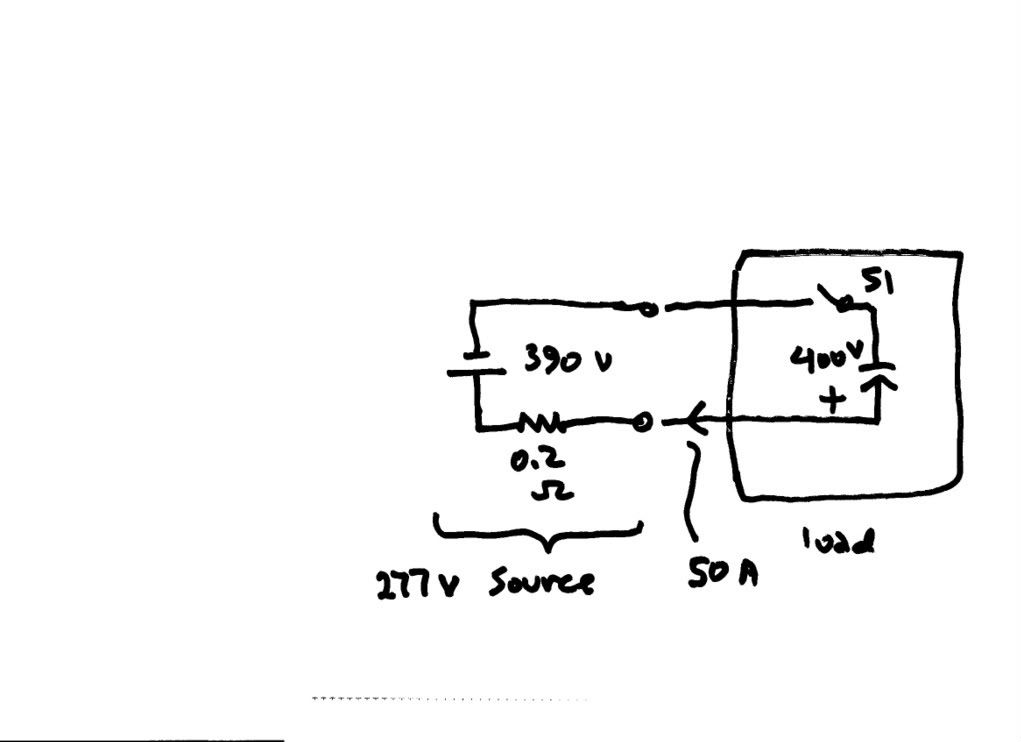
reversecurrent.jpg


Since we are dealing with instanteous values, I've shown the AC source as it swings negative as a battery equal to the peak value of 277v. The source impedance is 0.2 ohms.

The (I assume) switch-mode load has an internal capacitor of "zero" internal impedance, charged (possibly during the previous half cycle) to 400 v, with the polarity shown.
The switch S1 internal to the load closes momentarily, sending a 50 A pulse of current INTO the source; the source voltage momentarily goes to 400 v, hardly noticeable.

I'd say the capacitor switching circuitry inside the load is defective.

By the way, I'll try to get a hold of Dranetz' book on power quality. Maybe I can get it through interlibrary loan.
 
L

Lxnxjxhx

Guest
I rotated the photo in my album, but the edit didn't take.
 

catchtwentytwo

Senior Member
spsnyder said:
Should I be in the market for a new meter or is something else going on? Here's some snapshots of typical voltages and currents for A B C and N I just got back. Notice that the current is opposite the voltage oft times. This is a 208Y/120V panel in an office environment. I put the meter on because the 225 amp main breaker is tripping.

Thank you for your help.
Seeing how it is a Dranetz-BMI instrument, why not submit the waveform(s) to them here waveform@electrotek.com ? More on this service http://www.pqsoft.com/waveforms/index.htm
 

spsnyder

Senior Member
Thank you all for your responses. I figured out today that my clamp-on ammeter's max rating is 60amps, which is why the waveform is clipping at 70 amps. (dummy!) This might also explain the funky things going on.... I am going back and try to fit the larger clamp-ons on and look at the data. Will post back results either way. Thanks again.
 
L

Lxnxjxhx

Guest
one last thing

one last thing

If my analysis is right:

Normally we think of load as absorbing power from a source.
But, more generally, I'd say a load, ON AVERAGE, absorbs power from a source. If the load device stores energy, it can periodically return power to the source.
If a load returns power to a source ON AVERAGE, it's not a load.

I guess solar power arrangements can be a source and a load for PoCo.

This is just about the most interesting problem I've ever worked on. Usually I make a circuit to generate a waveform.
In this case, it's the other way 'round. Given the waveform, how do we "get there"?
 

wirenut1980

Senior Member
Location
Plainfield, IN
I've never seen this before, however I was monitoring phase to phase voltages and line currents on a small 240 volt drive. When I got everything hooked up I checked phasors to make sure it looked right. The monitor showed that phase A current and phase B current were in phase! In checking my CT's I noticed that they were set on 6000 Amp range. I flipped the switch to 600 Amp range and that fixed the problem. Not sure exactly why the currents appeared in phase, the current magnitude was probably too small to measure accurately. Kind of like seeing a very poor power factor while there is no load does not really mean anything...
 
Status
Not open for further replies.
Top