Site Lighting Voltage Drop

Status
Not open for further replies.
Good afternoon all,

I am trying to determine how to calculate VD and wire size for the following scenario. I have 89 (ttl)- 150w HPS fixtures 2 per location along a run of approx. 6000' from my panel. The voltage is 277 1ph.

I have tried Mike's calc sheet and seem to be doing something wrong. I have also read other FAQ's and am getting more and more confused about how to do this correctly.

Any help is appreciated.

Larry
 
Larry,

Are you coming up with approx. 500mcm copper? I would like to see other members chime in on this.
 
Last edited:
6000 feet of run and 89 - 150 watt rated fixtures...that is going to be some size conductor. Is the panel located at one end of the run or maybe in the middle?

I wonder who is the brain child of this design...maybe before I say this we can have some more info about the design of this installation.
 
A few qualifiers before I can figure this one out:

1. What does each 150watt HPS fixture draw for amperage at 277volts? (hint, I don't think 150/277 is correct) What does the nameplate say?
2. Are there really that many fixtures on one circuit? Who thought that scheme up?
3. Whatever the amp draw per unit is, you can't calculate the total load at 6000 feet, some are going to be closer to the source so the VD per unit will be less than those at the end. I think there's a formula for this in the American Electricians Handbook somewhere.

If you've got 277 volts, you've got 480 as well. Why not get 480volt fixtures if you can and reduce your VD? Number of conductors will be the same... two hots and a ground instead of one hot, one neutral and one ground.
 
Last edited:
480sparky said:
If you've got 277 volts, you've got 480 as well. Why not get 480volt fixtures if you can and reduce your VD? Number of conductors will be the same... two hots and a ground instead of one hot, one neutral and one ground.
Better yet, run them on a 3? circuit, which would require one more hot, but the loads could be networked across the three lines?30, 30, and 30(?)?and substantially lower the current on each line. I wrote in 30 ? 3 because the OP says 2 per location. 89 just don't fit that criteria!

1?, 1P, 277V circuit: 90 ? 150W ? 0.8PF(?) ? 277 = 60.9A
1?, 2P, 480V circuit: 90 ? 150W ? 0.8PF(?) ? 480V = 35.2A
3?, 3P, 480V circuit: 90 ? 150W ? 0.8PF(?) ? 480V ? √3 = 20.3A/line
 
Larry, I am with the others, something isn't adding up here.

In the FAQ on VD there is a link to another thread on this topic, here.


Essentially, since some of the load is shed at each stop, then the most accurate way to calculate the voltage drop is to take each segment between poles individually. Since we're talking about 89 poles, with 2 heads apiece, this is best suited for a spreadsheet.

Casting voltage drop itself aside for a moment, and just taking a ballpark guess at the current, we're probably talking in the neighborhood of 200A here.

  • 178 heads
  • Probably at least an amp per head (this is based on the label with the ballast - a typical 75W metal halide ballast draws around half an amp at 277)
  • 178 heads times 1 amp apiece = 178A

Are you planning on running a 200A feeder down the run, and tapping off with overcurrent protection at each pole?
 
Parking lot voltage drop calcs can be different than regular voltage drop calcs.

One large load 6000 feet from the panel is quite different than 89 small loads at varying distances from the panel, with the furtherest one being at 6000 feet. For this reason, I absolutely like to see a site lighting layout to do the voltage drop calcs. You can do a calc for each "branch" and do something of a radial wiring arrangement, and you can also size a large conductor to get you most of the way with little VD, then switch to somewhat smaller stuff between the lights to maintain the low VD.

In my opinion, when you're attempting VD calcs for site lighting, you need to start with the plan and your plan wheel.
 
I agree with Marc here, you need to start with the site plan first, unless you are taling about a road then that a different story.

I use a program called EDR, or "Electrical Designers Reference" and it has a "series" voltage drop calculator that allow VD to be calculated segment by segment...really works great and simple to use. http://www.edreference.com/
 
Sorry for my delay in getting back to you all. Thanks so much for the help. Here is some more info. This is multiple circuited with every 3rd light pole on a circuit spread out along the run. It is a secured detention facility and has no designer only a DGS reviewer. The service is set up mid way in the property and I will be feeding in multiple directions to accomplish this. The 277is being used because we have restrike fixtures and the quartz cannot be fed with 480v. I am trying to figure out the best scenario to get this done. The voltage drop is very confusing to me, especially the reduction in conductor size the farther away you get. I understand the principle and concept just not the calculations.

Thanks again- Larry
 
mdmasterelectrician said:
...The voltage drop is very confusing to me, especially the reduction in conductor size the farther away you get. ...

You mean the size of the wire gets smaller the further out you go??? That's going to really increase your voltage drop!
 
480sparky said:
You mean the size of the wire gets smaller the further out you go??? That's going to really increase your voltage drop!
No, as long as it's done correctly. That last run will only supply one fixture (or one pair; it's not clear), the next to last run will supply two, etc. You don't need full conductor size to the end. To calculate it, though, you have to start at the supply end.

Using the initial voltage and total current per conductor, you come up with an adequate conductor size. At the first drop, you figure the voltage there, and the remaining current per conductor. This continues, one step at a time, until you get to the end.
 
mdmasterelectrician said:
I understand the principle and concept just not the calculations.
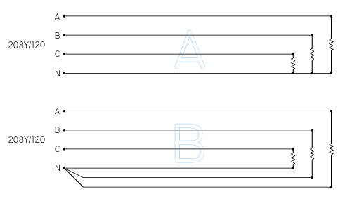
First, I would like to point out a consideration for determining the voltage drop of multiwire branch subcircuits which can reasonably be expected to be on/off simultaneously.

Consider the situation depicted in the following image. Though labeled 208Y/120, the same situation applies to 480Y/277. When loads, distance from source, etc. on each A, B, and C lines are equal, the voltage drop in scenario "A" is half that of "B".

VD.gif


In short, if you keep the "imbalance" current on your netral conductor(s) at or near 0A, you only have to consider voltage drop on the line conductors and the current on the neutral conductor run between balancing loads. Otherwise, voltage drop will be increased due to current to the source on the neutral conductor and life expectancy of both fixtures and lamps will be decreased.

The service is set up mid way in the property and I will be feeding in multiple directions to accomplish this. I am trying to figure out the best scenario to get this done.
Right now I'm picturing a circle of 6,000 ft circumference with the power source located at the center. Please advise as to the correctness of this picture... and provide a vivid description!!! Is this perimeter illumination, such as along a fence line, or is it array lighting such as poles at grid intersections...

This is multiple circuited with every 3rd light pole on a circuit spread out along the run.
Please elaborate. Footage between poles, for example. Exactly how many poles... is it 89 poles with two luminaires each, or what? Provide fixture nameplate info and/or fixture manufacturer, model no., etc... Withholding info is only going to make it harder.

The voltage drop is very confusing to me, especially the reduction in conductor size the farther away you get.
We'll get to this if needed or desired... however it would be easier on all involved here to contribute on the actual rather than continue/start speculating on some phantom set up.
 
mdmasterelectrician said:
This is multiple circuited with every 3rd light pole on a circuit spread out along the run. ..... The service is set up mid way in the property and I will be feeding in multiple directions to accomplish this.

What I envision is spokes on a wheel, the power source being at the hub and the fixtures along the rim. If you have several runs leaving the center, there's no need to put them all on one (as originally posted) or just three (as stated by the OP in his response).
So instead of 89 fixtures being fed with 1 or 3 circuits, is there the possibility of feeding each 'spoke' with it's own one or three circuits? If you have, for instance, 4 homeruns to your source, you're now dealing with only twenty-some fixtures per circuit to contend with.
 
Last edited:
Status
Not open for further replies.
Top