solar feed to multiple transformers

Status
Not open for further replies.
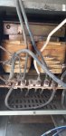
I have been asked to install 9kW of solar at a site that is a large farm. They have 240/480 split phase with 4 step down transformers that provide 120/240 at the four areas of the farm where they consume electricity. I will be putting the solar at one of the four areas of consumption and much of the production will be used there, but the excess will flow back through the local transformer. I really do not know much about transformers and want to be sure that this will not cause any problems. Most of the equipment is old as the original installation was 40 years ago. Any comments would be helpful.
 
Interesting setup. Is the 240/480 customer owned or utility? If the former, then I assume you have a service disconnect that then feeds the 4 areas?

It would be nice to connected directly to the 480, but I believe you will not find an inverter that will do that. So then it seems you have two options, connect to "half" of the 480, or connect to the secondary of the transformer.

I like the idea of NOT connecting through the transformer for efficiency and voltage Rise issues. You would need an inverter that can connect to 240 "Delta" (not center grounded) but I think most do. I know sunny boy does. You would not be distributung the load across the entire serving transformer winding, but you are only talking 9kva so likely not an issue.

I have 16kva of solar connected thru two transformers (and then ultimately the POCO transformer). Fortunately they do have taps so I can make it work fine, but if I didn't have the taps , I would have issues with over voltage from excessive "rise". These are not new transformers (like yours sounds like) so the voltage regulation is not the best.
 
Just to clarify, it would not cause significant problems to connect on the secondary side? The fact is that most of the production would be direct consumed in that area of the farm. There will be times when the production will exceed the use on the secondary side of the transformer and that will result in a backfed flow through the transformer, possibly once in a while as much as 8kW.
 
Does the transformer have taps? I would just be nervous about excessive voltage Rise. If the POCO already has high/variable voltage, you have a long/small aerial secondary run and an old transformer with poor voltage regulation, then those factors could all add up to over voltage being an issue. May want to just provide that disclaimer to the customer and/or investigate it a bit more. If you have taps you are probably all set.
 
As a start, you could measure the voltage and current out of the transformer secondary under no load and full load. From that you can get the impedance and the amount of voltage rise that would occur with the 8 kVA backfeed that you mentioned. Then see if that amount of voltage rise above the unloaded voltage would be acceptable with the inverters that you are considering.
 
I am afraid that I must admit to not knowing how to tell what I have. I understand the idea of taps, but not the practical.

What taps are, are methods for you to fine-tune the voltage rating, to adapt to grid voltages that vary from nominal. Depending on the specifics of the transformer, it could mean you physically wire to a different terminal, as is likely the case for a transformer that is 600V and less on both sides. Or it could mean you adjust a knob that selects the tap, as is common for medium-voltage transformers. Taps are on the side the manufacturer designates as primary, which they intend to have connected toward the utility. You set your tap to the prevailing percent error from nominal voltage, so that the secondary coil ends up operating as close as possible to nominal voltage.

What is really happening behind the scenes, is that you are either engaging or disengaging the windings of the transformer. Suppose you had 40 windings at nominal voltage (because that makes the math easy), and had +/-2.5% and +/-5% taps. At +5%, you have 42 windings engaged, and 41 windings engaged at +2.5%. The opposite happens for below nominal taps, where the -5% tap means 38 windings engaged, and the -2.5% means 39 windings engaged. Engaging fewer windings is how you adapt to lower than nominal voltage, and engaging more windings is how you adapt to greater than nominal voltage, and it is proportional to the ratio from nominal.
 
Thank you all very much. I will be on the site tomorrow and will check voltages with different current flows. I think the inverter can live with a wide variation of voltage but I will contact tech support and see what they say.
 
Older and smaller transformers can have issues with reverse feed. If the transformer is large in comparison to the inverter size it's less of an issue. You want to make sure that the circuit all the way back to the service entrance can handle the inverter output just in case all the loads are off and the PV system is still in production. If the utility does not allow energy back feed through the service entrance then you will have to come up with a plan to prevent that. If you can hand draft a rough single line that might be helpful.
 
If I understand correctly, the proposal was to feed one half of a 240/480V single phase feeder with a 240V inverter. How about using two smaller 240V inverters to feed both halves of the feeder? Any reason that wouldn't work? Advantages/disadvantages?

Cheers, Wayne
 
If I understand correctly, the proposal was to feed one half of a 240/480V single phase feeder with a 240V inverter. How about using two smaller 240V inverters to feed both halves of the feeder? Any reason that wouldn't work? Advantages/disadvantages?

Cheers, Wayne
Well I threw that out as a possibility, figuring it would be better to avoid the transformer losses and extra voltage drop/rise. Although I missed that OP said he thinks most PV energy would be consumed in site, so maybe it does make more sense to have it on the transformer secondary.
 
So maybe the OP isn't going to connect on the transformer primary side, but in a different situation if it were desirable to do so, my questions still stand.

Cheers, Wayne
 
So maybe the OP isn't going to connect on the transformer primary side, but in a different situation if it were desirable to do so, my questions still stand.

Cheers, Wayne

The only disadvantage I can think of for two inverters connected L1-center tap and L2-center tap is cost. For example, just checking one of my suppliers a sunny boy 7.7 is $1330, while two 3.8's is $1964. Of course there is some extra labor and components to hook them up. You get more MPPT's though may be beneficial. For one connected "off center" I dont really see any issue as long as the transformer is large enough. One potential disadvantage is due to the prevalence of reduced neutrals in single phase stuff, there would be more losses and voltage drop.
 
The idea is to connect on the secondary side of the transformer. The supply from the grid is 240/480 split phase and the transformer provides 120/240 split phase. Although much of the PV output will be consumed on the secondary side where it is connected, some will backfeed through the transformer to another area of the farm. I will be out there in the morning to get more info on the transformers and take some measures of voltage.
 
The idea is to connect on the secondary side of the transformer. The supply from the grid is 240/480 split phase and the transformer provides 120/240 split phase. Although much of the PV output will be consumed on the secondary side where it is connected, some will backfeed through the transformer to another area of the farm. I will be out there in the morning to get more info on the transformers and take some measures of voltage.
cool, let us know what you find. try to get transformer impedance and KVA, and a measure of secondary voltage with and without load.
 
The only load on the transformer is a large water pump. With no load the primary side was 463V and the secondary was 231V. With a draw of 25.3A the primary was 459V and the secondary was 227V. Here is a photo of the transformer.
 

Attachments

  • transformer1.jpg
    transformer1.jpg
    545.4 KB · Views: 9
So you have a 231V - 227V = 4V or 1.7 percent voltage drop with a 25.3A load.
The source impedance looking into the secondary of the transformer is 4V / 25.3A = 0.1581 ohms.
With 8 kVA of backfeed the no-load 231V will increase to 236.35V, which is a 5.35V or 2.3 percent rise.
That doesn't sound bad. You might want to utilize taps to increase the voltage somewhat if the loads are designed for 240V nominal.
Yeah sounds like the OP will be in good shape. Typically over voltage is the issue for inverters. The voltage range is not centered on 240 volts and has a much larger window on the low side. The typical acceptable voltage for a 240 inverter is 211-264


Hold on I just noticed OP is in Guatemala, what is the nominal voltage there?
 
Status
Not open for further replies.
Top