Solar tie to 100A breaker exception?

Status
Not open for further replies.

WaveGuide

Member
My friend's house has grid tied solar. Now here's the kicker:

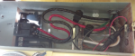
It ties directly to the exterior main service panel which only has a single 100A breaker.

The 100A breaker feeds both an interior service panel via some very large wires (I think they are #1 ga), and the solar's breaker box via #12ga wires, but with no breaker (other than the 100A breaker) between the 100A breaker and the solar breaker.

The #12 wires are tapped into the #1 wires just downstream of the 100A breaker with something that looks like a cable clamp.

In other words the #12 wires are protected only with the 100A breaker!


AC MAINS ==>
100A Breaker ==>
#1ga wires ==> Interior service panel
& #12ga wires---> Solar 20A breaker


It is my understanding that all wires must be protected upstream by a breaker of appropriate size to protect them.

In this case the #12 wires have only a 100A breaker upstream.

This doesn't seem sensible, nor reasonable, nor legal to me. But what do I know? Perhaps there is some code exception that I'm not aware of, but I don't think so.
 
Since there is an upstream disconnect, the #12 wires are not service conductors. They would have to be feeders.
The feeder tap rules allow 10' and 25' or less lengths of feeder to be protected by OCPD at the far end from the supply.
But I doubt that the wires in question meet those conditions.
The same wires, but with the 20A breaker at the supply end would be perfectly compliant. IMHO the service side, not the inverter side, is considered to be the supply side for those wires, since the inverter output is strictly current limited.

The "like a cable clamp" tap might be a listed insulation piercing connector, but more likely is a hack.
 
Last edited:
photo attached of inside exterior main service panel (rotated to meet website limits)

photo attached of inside exterior main service panel (rotated to meet website limits)

Thanks for the technical terms. I figured out how to post a photo.

Yes, I am talking about the heavy red & black "S" shaped "feeders" shown in the photo leading from the main service panel's 100A breaker (left in photo, top in actuality), to the interior distribution panel (not shown), and tapped (black taps) inside the main service panel to #12 wires going to the solar breaker box (not shown).

I looked again. It looks like the taps are done with a listed insulation piercing connector.

.. the service side, not the inverter side, is considered to be the supply side for those wires, since the inverter output is strictly current limited.

Ok. But not sure what you mean by:

.. feeder tap rules allow 10' and 25' or less lengths of feeder to be protected by OCPD at the far end from the supply.

BTW, there is a 110V outlet box directly below the service panel for the sprinkler control power. It's supplied through what looks like a black in-line fuse (shown in the bottom of the box in the photos). I've never seen that before. Not sure what to think of it. But at least it's protected.
 

Attachments

  • 20170312_093147b.png
    20170312_093147b.png
    135.8 KB · Views: 0
Seems like a compliant tap to me as long as it is 10ft or less. If a 10ft tap then 20A is more than the 10 percent required by 240.21(B)(1). Under the 2011 NEC or earlier it could be interpreted that it was allowed to load the feeder up to 120 percent of it's ampacity. Assuming 12awg means a 20A solar breaker (if it's greater, then that is the violation), then there you are, 100+20. Under the 2014 or 2017 code the installer would be required to put a 100A breaker downstream, e.g. a main breaker in the panelboard fed by that feeder. (Unless, that is, those feeders are 1awg or bigger).

My questions are...
- Is that not another spot for a service disconnecting breaker to the right of the existing 100A? If yes, why not just use that? (If not, what is that slot? It does look a little weird to me.)
- What is that socket and plug looking thing at the bottom of the panel? :lol:
 
Ok, thanks to both of you for straightening me up.

The tip as to which code to look up helped me greatly to find this: https://www.youtube.com/watch?v=uJRSrB4E7dY which then further helped me not only understand what the code said, but why.

Yes the tap is <10', and 20A, and in a raceway, so the 12ga is ok. What I didn't understand at first, was that a short in this wire would clear the 100A breaker. I was confused thinking it would melt the wire, but that could only happen if the continuous load exceeded 20A, which a short would not.

Anyway thanks again! Sure appreciate the help.


Re: My questions are...

>- Is that not another spot for a service disconnecting breaker to the right of the existing 100A? If yes, why not just use that? (If not, what is that slot? It does look a little weird to me.)

I looked at that too. It does appear to be a slot, and has a metal contact at the top. Perhaps you are right. I'll investigate it with a meter tomorrow (as a possible way to clean up the silly inline fuse you asked about below.

>- What is that socket and plug looking thing at the bottom of the panel? :lol:
 
Status
Not open for further replies.
Top