Split Phase Motor Mystery

Status
Not open for further replies.

autonow

Member
i have a Single phase, split phase motor 1/3hp wired for 220Volt operation. When It starts it will not develop much starting torque, and almost takes the full 6 seconds to click in the centrifugal switch.
When it clicks in it seems to have the full Hp rating available.

If I rewire the motor for low voltage and plug it in to a 120Volt outlet it runs fine and clicks in the switch in 1-2 seconds.

I have tried several motors with the same response..

Whats going on? How do I make my motor run?

Clues.. I have a 3 phase corner grounded supply 230Vac. I am using 1 leg and the corner grounded leg. The corner grounded is connected to the L2 terminal. L1 is the ungrounded wire as specified on the nameplate. I measure 230 across the 2 wires. I do not want use the two ungrounded legs for safety. Since it is a corner grounded delta, low voltage is not available from this source.
 
Last edited:
One of the two starting windings may have a high resistance that allows the motor to start well when they are in parallel but does not conduct full (or any) current when wired in series.
Get out your ohmmeter.
That does not explain multiple motors with the same problem though unless you are miswiring them in the HV connection.
The size of the starting capacitor will also be a compromise between the two configurations.

Sent from my XT1080 using Tapatalk

A true "split phase" motor should not have a capacitor, the start winding just has a different reactance than the main winding to create a phase shift, and they generally have much less starting torque than a capacitor start motor. But I do have to wonder if it is possibly being wired incorrectly when changing to hi volts connection.

It is also likely that the start winding is only a 120 volt winding and when connected to 120 volts you have all three coils, 1 start winding coil and 2 main winding coils all wired parallel to one another. When connected to 240 volts you will have the two main winding coils wired in series and the start winding will be parallel to one of those windings. This in itself may lead to harder starting if the starting torque demanded by the load is on the high side for a split phase motor, as you will not get the same kind of current/voltages across each winding as you do when each has a full 120 across it.

I can't say I have much experience with 230 volt connected split phase motors, as they are often only about 1/3 hp max and are almost always connected to 120 volts even if they are a dual voltage motor, and almost always are driving a fairly low torque demanding load.
 
Wiring

Wiring

I thought about the correct wiring....

Motor 1 the motor that works on 120 but not 230 is a dual voltage motor.

I have tried 4 other motors that are 230 Volt only, these were old and in the recycle bin and may have had issues to begin with. But all would eventually get to speed. Since they were single voltage I could not try the low voltage

Then there is the NEW motor that I bought to replace the first one. It came prewired for 230 same issue This was before I tried wiring the first motor for 120 and found it ran well.

The only thing I can think is there is some wiring mystery on the winding connected to the L2 terminal. In a single phase system 220V system it is ungrounded and you have a separate ground to the frame. The recycle motors did run ok in a 3 phase Y system at one time before they found the recycle bin.
Since a corner grounded delta, the ground is one of the "phases" I wanted to know if anyone thought this could be the problem. I never tried the motor on the 2 ungrounded legs. Just did not like the idea of no ground!
motor windings are not going to care what is grounded and what is not, outside of the winding insulation withstand ratings, but they likely have enough insulation that you could have maybe 600 volts to ground and it would still run as long as proper voltage was between input leads.

I still have a curiosity of what I mentioned earlier about the start winding being only a single 120 volt coil and is connected to one line and the "center tap" of the main winding when configured for 240 volts. I can easily see the start winding not getting a full 120 volts when connected this way, unfortunately many motors are connected this way. A capacitor start motor is probably much more immune to such effects but a real split phase with no capacitor will not have very high starting torque and I can see it being even worse if the start winding is not seeing full design voltage.

Can you connect a volt meter to each end of the start winding and see what kind of voltage is being imposed across this winding during starting? When connected for 120 volts it will always be same as the input voltage, because it is directly connected to incoming lines in this configuration.

I like what you say about the start winding, In the 240 config the start winding might actually have 0 volts across it! Since it is trying to make that 120Volt coil and their is no separate ground or (different ground) than the supply leg. In a 3phase Y you can get the 120 to ground but not on a corner grounded system. In a 120 system you can have 3 120 coils (2 in series) and 1 for start, It does make sense!
 
I like what you say about the start winding, In the 240 config the start winding might actually have 0 volts across it! Since it is trying to make that 120Volt coil and their is no separate ground or (different ground) than the supply leg. In a 3phase Y you can get the 120 to ground but not on a corner grounded system. In a 120 system you can have 3 120 coils (2 in series) and 1 for start, It does make sense!
There is 120 volts to the "midpoint" of the run winding, because each half is equal impedance. But tapping that start winding there will throw it off balance, but not so far off that there is no voltage at all across the start winding. You have a series-parallel situation for the duration the start winding is in the circuit, can't say I do those kinds of calculations enough to know how off the top of my head, but very likely there are different voltages on all three coils during starting when connected for 240 volts, but they all have full 120 volts across them when connected for 120 volts, and as I said a capacitor start motor may suffer some of the same thing but has more starting torque and gets to speed faster and may not be something that is noticed as easily.
 
I like what you say about the start winding, In the 240 config the start winding might actually have 0 volts across it! Since it is trying to make that 120Volt coil and their is no separate ground or (different ground) than the supply leg. In a 3phase Y you can get the 120 to ground but not on a corner grounded system. In a 120 system you can have 3 120 coils (2 in series) and 1 for start, It does make sense!
I doesn't make sense. The motor only cares about voltage. Whether the ground reference is 120V or 240V is not relevant. I don't know of a 240V motor that needs a grounded conductor. You could use your two ungrounded conductors to power the motor and it would be perfectly safe, not any different than powering it from a single phase source.
 
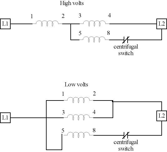
here is a schematic of each connection scheme:

In the low volt configuration each of the three windings are directly connected to the incoming supply lines, with a centrifugal switch to cut out start winding when a predetermined speed is reached.

In the high volt configuration each run winding is equal impedance and as long as centrifugal switch is open (when in run mode) each run winding coil sees half the applied voltage. But when the switch is closed allowing current to flow in the start winding that balance will be thrown off. The more torque the load demands the worse this will probably be and is why this kind of motor is not all that common as compared to a capacitor start motor.
 
Status
Not open for further replies.
Top