Some help please, for I have very little experience with x-formers.
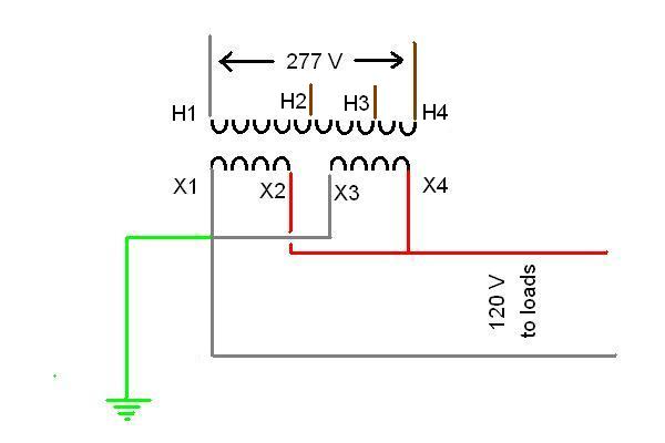
I've got a sign that used to be 277v. It was changed to 120v via a x-former - 208, 240 or 277 primary and 120-240 secondary. H1(277 hot) and H4(277 neutral) are the primary. The secondary was wired X2 and X3 together with the secondary neutral and X1 was hot and X4 was hot. Between X1 and X4 is 240v. Between X2-X3 and either X1 or X4 is 120v. But from X1 to ground is 18v or less. Same with X4 to ground.
The problem is this: There are 10 different ballasts on three diffenent switches, the sign has 3 sections with separate disconnects. 8 on one lead (A), 1 on one lead(B) and then one more(C). X4 feeds A and X1 feeds B and C. When sign A is on, sign C's power has 120v line-neutral, 240v line-ground. Turn A off and sign C is 120v line-neutral, 120v line-ground. Sign B isn't effected.
Something's wrong, right? So I changed the wiring of the x-former to the 120 diagram which is X1-X3 for the neutral and X2-X4 for the 120. When I do this I get 120v line-neutral but nothing line-ground and the neutral becomes energized. But all the signs work. Does this make sense? Do I make sense? Any input would be helpful.