Step-Up Transformer for a Sub-Panel Set-Up

Status
Not open for further replies.

nmonaco

Member
Location
Baltimore
Occupation
Civil Engineer
Under the following scenario, I would be running a 240v to 480v, 37.5 kVA step-up transformer (L1+L2) at 240v from a single phase 120/240v main panel. The step-up transformer would then power a 480v single phase panel, which would be running to a some 480v to 120/240v step-down transformers at the location of a few devices.

My questions are:
1) Can I size my service and main circuit breaker to the applied load, which would be 200A?
2) I need a 2-pole 200A circuit breaker as the primary-only side protection for the 37.5 kVA step-up transformer in order to meet 125% of the amperage per Table 450.3(B) of the NEC. Can I have a 200A circuit breaker on a 200A panel?
3) Can the sub-panel have a smaller main circuit breaker (100A) than the circuit breaker for the transformer (200A)? The sub-panel would be within 50 feet of the main panel
4) Does everything else seem fine with the line diagram and panels?

Thanks for any and all help. I genuinely appreciate any time you take to look this over and respond.
1627911023648.png
1627911376748.png
 
Under the following scenario, I would be running a 240v to 480v, 37.5 kVA step-up transformer (L1+L2) at 240v from a single phase 120/240v main panel. The step-up transformer would then power a 480v single phase panel, which would be running to a some 480v to 120/240v step-down transformers at the location of a few devices.

My questions are:
1) Can I size my service and main circuit breaker to the applied load, which would be 200A?
2) I need a 2-pole 200A circuit breaker as the primary-only side protection for the 37.5 kVA step-up transformer in order to meet 125% of the amperage per Table 450.3(B) of the NEC. Can I have a 200A circuit breaker on a 200A panel?
3) Can the sub-panel have a smaller main circuit breaker (100A) than the circuit breaker for the transformer (200A)? The sub-panel would be within 50 feet of the main panel
4) Does everything else seem fine with the line diagram and panels?

Thanks for any and all help. I genuinely appreciate any time you take to look this over and respond.
View attachment 2557415
View attachment 2557416
Your one line is virtually illegible. But I just have one question... why would you want to do this? 480v motors require 3-phase power.

AFAIK they don't make 480v single phase motors.

Sent from my SM-A326U using Tapatalk
 
Under the following scenario, I would be running a 240v to 480v, 37.5 kVA step-up transformer (L1+L2) at 240v from a single phase 120/240v main panel. The step-up transformer would then power a 480v single phase panel, which would be running to a some 480v to 120/240v step-down transformers at the location of a few devices.

My questions are:
1) Can I size my service and main circuit breaker to the applied load, which would be 200A?
2) I need a 2-pole 200A circuit breaker as the primary-only side protection for the 37.5 kVA step-up transformer in order to meet 125% of the amperage per Table 450.3(B) of the NEC. Can I have a 200A circuit breaker on a 200A panel?
3) Can the sub-panel have a smaller main circuit breaker (100A) than the circuit breaker for the transformer (200A)? The sub-panel would be within 50 feet of the main panel
4) Does everything else seem fine with the line diagram and panels?

Thanks for any and all help. I genuinely appreciate any time you take to look this over and respond.
View attachment 2557415
View attachment 2557416
But to answer your questions, yes, you can have a 200 Amp breaker in a 200amp panel, but I doubt they make one as it would be difficult to fit the frame of a 200 Amp breaker on the bus with other breakers.

And yes, the subpanels main breaker can be smaller than the rated output of the transformer.

Sent from my SM-A326U using Tapatalk
 
Your one line is virtually illegible. But I just have one question... why would you want to do this? 480v motors require 3-phase power.

AFAIK they don't make 480v single phase motors.

Sent from my SM-A326U using Tapatalk
It looks like he's wanting to go 240 to 480, then back to 240 to feed some devices
 
EDIT: maybe they make 200 Amp breakers for a 200 Amp panelboard but probably not a resi load center.

Sent from my SM-A326U using Tapatalk
 
EDIT 2: they do make bus tap devices that kind of look like a breaker frame but has no actual breaker, just lugs, but, again, probably only for panelboards for 200 Amp rated.

Sent from my SM-A326U using Tapatalk
 
Your one line is virtually illegible. But I just have one question... why would you want to do this? 480v motors require 3-phase power.

AFAIK they don't make 480v single phase motors.

Sent from my SM-A326U using Tapatalk
It is not illegible, but it does not make much sense. You could probably get a 480 V single phase motor if you had it custom made.
 
Sorry for the confusion everyone. The devices aren't motors, they would device cabinets that need to be powered at 120/240, so this:

It looks like he's wanting to go 240 to 480, then back to 240 to feed some devices

is exactly what I want to do.

You can have a 200 Amp breaker in a 200amp panel, but I doubt they make one as it would be difficult to fit the frame of a 200 Amp breaker on the bus with other breakers.

And yes, the subpanels main breaker can be smaller than the rated output of the transformer.
This is the exact info I wasn't sure about, so this was extremely helpful.

Thanks for taking the time to help me out with this.
 
Sorry for the confusion everyone. The devices aren't motors, they would device cabinets that need to be powered at 120/240, so this:


is exactly what I want to do.


This is the exact info I wasn't sure about, so this was extremely helpful.

Thanks for taking the time to help me out with this.
No problem. We're very curious though. May we know why?

Sent from my SM-A326U using Tapatalk
 
No problem. We're very curious though. May we know why?

Sent from my SM-A326U using Tapatalk

Absolutely haha. Sorry for being vague

These are device cabinets for ITS equipment along a highway. The runs can be very long, so I need to step-up and then step-down in order to use wire sizes that meet the right voltage drop.
 
2 comments:
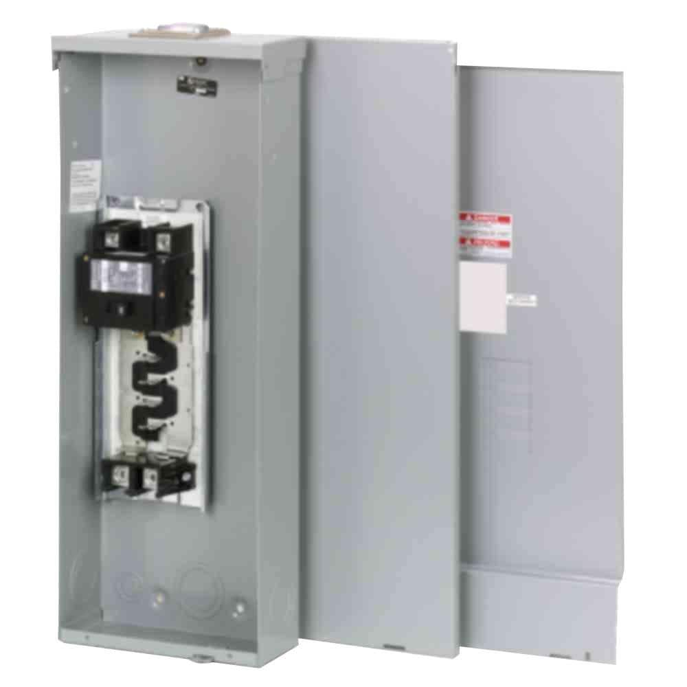
If the Main panel is not already in place you could use a 200 amp MB feed thru panel and feed the transformer from the lugs.
How are you providing the required protection for you individual step down transformers ?
 
2 comments:
If the Main panel is not already in place you could use a 200 amp MB feed thru panel and feed the transformer from the lugs.
How are you providing the required protection for you individual step down transformers ?

Sorry, I'm pretty new to some of this. I am not familiar with this set-up using lugs. Would you mind elaborating?

The idea for the primary-side protection for the step-down transformers would be the breaker in the sub-panel, and the secondary protection would be a breaker in the device cabinets... although I now see that I should change the breaker sizes in the sub-panel to match the transformer sizes: 15A for the 2kVA step-downs and 40A for the 15kVA step-downs
 
Sorry, I'm pretty new to some of this. I am not familiar with this set-up using lugs. Would you mind elaborating?

If you supply a "feed thru" panel (see catalogs) it will have lugs on the buss protected by the main breaker thus your 200 amp main breaker will also serve as the supply breaker for your transformer.
The idea for the primary-side protection for the step-down transformers would be the breaker in the sub-panel, and the secondary protection would be a breaker in the device cabinets... although I now see that I should change the breaker sizes in the sub-panel to match the transformer sizes: 15A for the 2kVA step-downs and 40A for the 15kVA step-downs

Correct. With 125% protection on the secondary side, you can go as high as 250% on the primary (no next size up).
Allows you to have multiple transformers fed by one feeder.

There are a lot of details on grounding,and other Code issues not addressed by your sketch. Hopefully you will get an EE involved for the final

(We will watch the mail for our 'design' checks :) )
 
Last edited:
There are a lot of details on grounding,and other Code issues not addressed by your sketch. Hopefully you will get an EE involved for the final

(We will watch the mail for our 'design' checks :) )


Hahaha I definitely owe this forum some commission with the help it has provided

I threw this sketch together pretty quickly as an example, so I didn't include any grounding information for the actual equipment. If there is anything glaring that is incorrect feel free to let me know. I will gladly take the opportunity to learn from everyone (but do not feel obligated, you have already gone above and beyond answering my question, which I am very thankful for)
 
Absolutely haha. Sorry for being vague

These are device cabinets for ITS equipment along a highway. The runs can be very long, so I need to step-up and then step-down in order to use wire sizes that meet the right voltage drop.
Makes total sense. I've used boost transformers in the past to compensate voltage drop.

Also use them to step up 208 to 240 for water heaters and ranges for full wattage output.

Sent from my SM-A326U using Tapatalk
 
Sorry, I'm pretty new to some of this. I am not familiar with this set-up using lugs. Would you mind elaborating?

The idea for the primary-side protection for the step-down transformers would be the breaker in the sub-panel, and the secondary protection would be a breaker in the device cabinets... although I now see that I should change the breaker sizes in the sub-panel to match the transformer sizes: 15A for the 2kVA step-downs and 40A for the 15kVA step-downs
 
Status
Not open for further replies.
Top