jrhopkins
Member
- Location
- Portland, OR
- Occupation
- Electrician
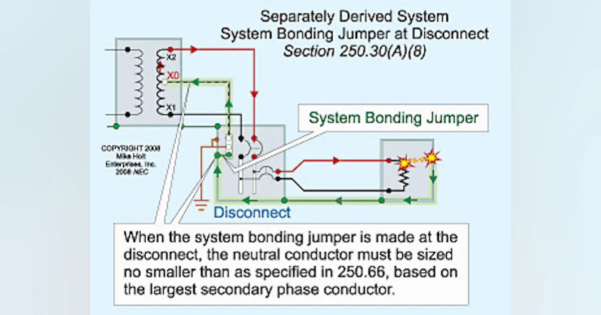
I work for a large manufacturing company. This company has it's own xfmr wiring schematic that they waterfalled to the AHJ and the electrical contractors on site. The inspector with the AHJ has told me in conversation that the city is not a fan of this new wiring method so the question I have is, is this new wiring method safe? The "new" wiring method is as follows. All grounds land under a common ground bar (nothing out of the ordinary), but instead of routing the secondary neutral to the "XO" the neutral for the secondary is instead landed at the common ground bar. The equipment bonding jumper is the only conductor that lands on the "XO", but the equipment bonding jumper is to be the same phase color and conductor size as the neutral for the secondary. This is a 480/277V primary, 400/230V secondary xfmr. It has me concerned about there now essentially being (2) "XO" termination points as landing the neutral for the secondary on the common ground bar essentially turns the ground bar into an auxiliary "XO" doesn't it? Since it is a code violation to land a neutral on the ground bar at the panel, why would it not be a code issue to land the neutral at the ground bar instead of the "XO" in the xfmr? I know that the neutral is created from the ground at the transformer, but something about this just doesn't sit right with me. The companies engineers have assured the AHJ and us contractors this wiring method is electrically sound, so I guess I'm just trying to make sure these engineers aren't putting myself, or my company in a compromising position with this wiring method.