Stray Neutral Voltage

Status
Not open for further replies.

AHE Tom

Member
Situation:

Stray neutral voltage as high as 90 volts (with a 2.7A potential) between ground/neutral bar in main house panel and the well casing (water system). The voltage increases on the neurtal when a load is applied.

Existing equipment:
200A main bkr 1ph residential panel (in residence) fed by utility co pad mount xfmr (only house on Xfmr), 100A sub feed panel in garage (seperate building). All grounding, bonding, neutral connections verified as per NEC.

Notes:
Utility Co said that there is a neutral problem, and that their equipment is ok (their equipment never fails)

All 1 phase circuits were removed from the panels and meggered out and are ok.
All heating circuits removed from panel meggered out and are ok
All other circuits (stove, water heater, well pump ckting, etc.) were removed from the panels meggered out and are ok
Disconnected sub feed cable and meggered it out and is ok

Well pump (240V) is served via a 2 wire connection from the pressure switch to the pump, no ground wire, and well casing was not grounded.

Reconnect ONLY the heating circuits (all 240 2 pole circuits) verify current is equal on both poles at branch breaker and on line side of main breaker.

As each heating circuit is turned on the voltage between the neutral bar and the well casing increases as the indavidual heating circuit is turned on.

It appears that as load is applied to the electrical service (straight 240 1ph laods only) some how the system is generating a voltage on the neutral that the transformer's neutral can not accept, and that the water system (well casing) is a better source of ground than the xfmr it self.

A ground conductor was installed from the neutral/ground bar in the main panel to the well casing and this is disapate the voltage generated as temporary fix.
The utility co. is comong back to review the problem also

I was just looking for ideas from this forum as to what could be causing this.

Thanks
 
So if you place a meter between the well casing and house panel main neutral ground bond you read 90 VAC?

With pump on and off?
Did you place a lamp between the casing and neutral bond?
Did you ground CAREFULLY the well casing?
Did you check the pump?
What type of meter?
 
Stray neutral voltage as high as 90 volts (with a 2.7A potential) between ground/neutral bar in main house panel and the well casing (water system). The voltage increases on the neurtal when a load is applied.
?

Well pump (240V) is served via a 2 wire connection from the pressure switch to the pump, no ground wire, and well casing was not grounded.
?

A ground conductor was installed from the neutral/ground bar in the main panel to the well casing and this is disapate the voltage generated as temporary fix.

Strange at first glance I thought the well pump is shorting but if you have installed a separate EGC from the service disconnects ground bus to the well pump starter and casing this should provide ground fault path. You could/should have substantial load on this with a large amount of 110V running if the utility has lost their neutral.

Check the service disconnects neutral bond, make sure it is terminated. It may be the utility companies XO or grounded conductor terminations.
 
If the utility has lost their neutral you should be able to turn on some 110V load and measure voltage at the service disconnects neutral bus to earth ground. You can do this test ignoring the well altogether. The returning current will be roaming through many paths looking for its source ?XO?, it will be using earth because the service transformer is grounded.
 
081121-1932 EST

AHE Tom:

I am not clear on your circuit description, but it points to a neutral problem.

Following is a troubleshooting sequence you might try:

Be very careful because there may be a high voltage (120 to 240 V) low impedance power source that could produce a sever shock.

1. Find a conductive pipe that runs in the earth at least a few feet to serve as a voltage reference point. If one does not exist drive some metal rod into the earth in a convenient location. Attach an insulated wire to this reference rod of adequate length to reach any point where you want to make a voltage measurement. I use a three conductor extension cord. A Fluke high impedance digital voltmeter is very good for the meter.

First, do experiments with the main panel breaker open, second do it with the breaker closed and a 10 ohm resistance (1500 W 120 V heater) as the only system load between neutral and a hot line.

2. Use a long insulated handle screwdriver as a probe. Insert it a couple inches in the earth at any test point and measure its voltage relative to the reference electrode in (1) above.

At any place in my yard I am below 1/2 V unless I intend to create a ground current.

Measure near the service transformer, near the service entrance, and any other spot that seems reasonable. Record these values and their location.

3. If the meter box is metal check its voltage.

4. If there is an ouside outlet, then check the voltage to each terminal

5. In the main panel check the voltage to the enclosure, to each end of the neutral bus, and to each end of the EGC bus, and each hot line.

6. By this point there is a high probability you can find the problem. Which is probably between the main panel and the supply transformer. Although one poster on this web site had a broken bus in the main panel. That is the reason for measuring the voltages at each end of each bus.

7. A 0000 copper wire 100 ft long has a resistance of 0.005 ohms. A 10 A current thru this would produce a voltage drop of 0.05 V, and 100 A 0.5 V. You can look up wire resistance for smaller wire and aluminum and do your own calculation.

.
 
Yes, only when 65 amps worth of baseboard heating (240V) is turned on, and the voltage will go up incrementally as the heating circuits are turned on.


So if you place a meter between the well casing and house panel main neutral ground bond you read 90 VAC?

With pump on and off?
Did you place a lamp between the casing and neutral bond?
Did you ground CAREFULLY the well casing?
Did you check the pump?
What type of meter?
 
The neurtal voltage that is being read is when only 240 volt heating circuits are on. I wanted to proove to the utility co. that the problem is not being generated by a 110 1 phase circuit or 120 volt appliance in the residence.

I feel that their pad mounted xfmr neutral is breaking down. They supposedly checked the neutral connections in the meter and at the xfmer and said all is good, but thay only tested it with a 15 amp load.


Strange at first glance I thought the well pump is shorting but if you have installed a separate EGC from the service disconnects ground bus to the well pump starter and casing this should provide ground fault path. You could/should have substantial load on this with a large amount of 110V running if the utility has lost their neutral.

Check the service disconnects neutral bond, make sure it is terminated. It may be the utility companies XO or grounded conductor terminations.
 
If I disconnect the 240 volt loads, and connect say a lighting circuit with around 7 amps worth of load this will also increase the neutral voltage say 4 volts.
It appears that it does not matter if it is a 240 volt load or a 120 volt load, as long as the system is loaded the neutral voltage will increase.

As I said before I initially loaded the system with straight 240 volt loads to indicate to the utility co. that the residence's electtrical 120 volt circuits are not causing a NEUTRAL problem, because there is no neutral in a 240 volt heating circuit.

Doy you agree ?


If the utility has lost their neutral you should be able to turn on some 110V load and measure voltage at the service disconnects neutral bus to earth ground. You can do this test ignoring the well altogether. The returning current will be roaming through many paths looking for its source ?XO?, it will be using earth because the service transformer is grounded.
 
To keep the initial post shot, I did not indicate the testing I have done. I have done some of the testing that you have indicated, and after much consultation with some other local engineers, electrical contractors, and two factory reps (GE, and Square D), all have pretty much come to the conclusion that the utiltiy co. underground feeder, xfmr, or the primary feed is breaking down.

For Penelec to fix this I must proove to them that I am correct though. Like I said the utility co.s equipment never fails, just ask them !


081121-1932 EST

AHE Tom:

I am not clear on your circuit description, but it points to a neutral problem.

Following is a troubleshooting sequence you might try:

Be very careful because there may be a high voltage (120 to 240 V) low impedance power source that could produce a sever shock.

1. Find a conductive pipe that runs in the earth at least a few feet to serve as a voltage reference point. If one does not exist drive some metal rod into the earth in a convenient location. Attach an insulated wire to this reference rod of adequate length to reach any point where you want to make a voltage measurement. I use a three conductor extension cord. A Fluke high impedance digital voltmeter is very good for the meter.

First, do experiments with the main panel breaker open, second do it with the breaker closed and a 10 ohm resistance (1500 W 120 V heater) as the only system load between neutral and a hot line.

2. Use a long insulated handle screwdriver as a probe. Insert it a couple inches in the earth at any test point and measure its voltage relative to the reference electrode in (1) above.

At any place in my yard I am below 1/2 V unless I intend to create a ground current.

Measure near the service transformer, near the service entrance, and any other spot that seems reasonable. Record these values and their location.

3. If the meter box is metal check its voltage.

4. If there is an ouside outlet, then check the voltage to each terminal

5. In the main panel check the voltage to the enclosure, to each end of the neutral bus, and to each end of the EGC bus, and each hot line.

6. By this point there is a high probability you can find the problem. Which is probably between the main panel and the supply transformer. Although one poster on this web site had a broken bus in the main panel. That is the reason for measuring the voltages at each end of each bus.

7. A 0000 copper wire 100 ft long has a resistance of 0.005 ohms. A 10 A current thru this would produce a voltage drop of 0.05 V, and 100 A 0.5 V. You can look up wire resistance for smaller wire and aluminum and do your own calculation.

.
 
I appreciate all the help and ideas that has been provided by everyone, this is going to be a tough one to crack, and I will solve it with help from all your input.


Thanks again
Tom
 
081122-1142 EST

AHE Tom:

Your utility transformer has a center tapped secondary that supplies the 120-0-120 V to the service drop. The center tap is called neutral and should be connected to a ground rod at the transformer pad or pole.

From the transformer center tap a heavy wire, probably between a 0 and 0000, is run to the meter and then to the main panel neutral buss and in the same panel is a ground buss connected to the neutral buss. From the ground buss in the main panel a heavy wire, grounding conductor, to a ground electrode which may be a ground rod.

All of these heavy conductors from the transformer center tap to the neutral bus and to the two grounding electrodes normally have a low impedance. Note, the ground rods to earth do not generally have a low impedance. The impedance (AC opposition to current flow) which is close to the DC resistance of the conductors is designed by the choice of wire size to have an acceptably low voltage drop at maximum load current. If we assume 2% as acceptable for this voltage drop along these conductors at full load, then the voltage drop should be less than 2.4 V at 200 A if it is a 200 A service. At a 10 A load it would be 0.12 V, or a resistance of 0.12/10 = 0.012 ohms. Also note that transformer internal impedance may be higher than the service drop.

If the ground rod at the transformer has good connections to the transformer center tap, then a measuring probe in contact with that ground rod or very close to it in the adjacent earth will be close to the potential of the center tap. If you measure the voltage from said probe to the neutral bus in the main panel and you get voltages greater than expected, like moderately greater than my above estimates, but based on calculations based on your wire size, then there is a problem in the neutral path. However, this does not necessarily test for a poor neutral connection to the transformer center tap.

If the neutral appears to be good based on the voltage drop measurement from the utility ground rod to your main panel neutral bus, then how can you determine if the transformer center tap to neutral wire connection is good? Measure the voltage from the utility ground rod to one of your hot lines, but pick the hot line that you do not load. Now apply a load and see if there is an excessive voltage change. Excessive means something moderately larger than what you predict the neutral voltage drop to be for the applied load. If I expect to get 0.12 V change over the neutral with a 10 A load from neutral to the above defined hot wire, and the change is even as low as 0.5 V (a ratio of 1 to 4), then I might expect a problem at the neutral to center tap connection.

When I measure the voltage from the transformer center tap to one hot wire, monitored side, and load the opposite hot wire to neutral I should see substantially less change in the voltage on the monitored side than on the loaded side.

On a small transformer I found the change in voltage on the monitored side to be 1/3 that on the loaded side. This mutual effect is a result of the leakage inductance of the transformer.

If you eliminate all loads on one side of neutral and heavily load the other side, then what is the voltage drop across the heavy load? Is this way below 120 V? Then you need to determine if the major voltage drop is on the hot side or the neutral.

Some measurements at my home today. My test load is a 1500 W heater, about 10 ohms, and thus about 12 A load. Unloaded to loaded change on side A, 122.87-121.80 = 1.07 V. Monitoring B side and loading A side 121.87-121.80 = 0.07 V. Unloaded to loaded change on B side 121.87-120.40 = 1.47 V. It is cold outside and I do not want to check voltage drop from pole ground rod to house water line, but it will be small. I do not like my pole transformer internal impedance, but I live with it. I also get a change of 43 MA in earth current for 12 A load change. Thus, my ground path resistance 12000/43 = 280 times higher than my neutral wire path.

If you have an open neutral wire and good connections from the transformer center tap to its ground rod, and from your main panel neutral bus to the home grounding electrode, then this ground path will be a high impedance neutral conductor and neutral current will flow thru it.

I think some electrical circuit theory courses would be of help to you to understand the various means to troubleshoot this type of problem.

.
 
I did the same 1500 W heater test at my house during the Spring. But I looked at the results as Source Impedance of the POCO wiring. My house was about 0.07 Ohm Source Impedance, using your numbers:
E/I = R (I know that it's "Z" but with a resistive load, it works out OK)
1.07V / 12A = 0.09 Ohm Source Impedance
1.47V / 12A = 0.12 Ohm Source Impedance

Last Christmas Week the POCO replaced the jumper cable from the 7800 Volt transformer to the lines that feeds about 14 old houses. The jumper lit-up like a Christmas light, the 5 foot jumper had about 5 splices some aluminum some copper.
It looks like your house is less good than mine.
 
?
It appears that it does not matter if it is a 240 volt load or a 120 volt load, as long as the system is loaded the neutral voltage will increase.

As I said before I initially loaded the system with straight 240 volt loads to indicate to the utility co. that the residence's electtrical 120 volt circuits are not causing a NEUTRAL problem, because there is no neutral in a 240 volt heating circuit.

Doy you agree ?

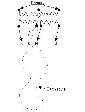
Yes I agree, I think the center tap ?XO? of the serving transformer is open. This could explain why the problem shows up with only 240V load (no neutral).

Please let us know the results, I am curious.
 
I'd say you are about to witness one of the miracles of electricity.
POCO will check their equipment, assure you that they found nothing wrong and completed no repairs, but,...... the miracle...... the problem will no longer exist.
 
If the XO is open at the windings the transformer needs to be replaced, the break may no be accessible.

Have the utility company meet you on site and lift the transformer ground first. If 240V circuitry is relying on earth to complete the path between X1 & X2 this test will prove it.
 
TransformerXO.jpg
 
I'd say you are about to witness one of the miracles of electricity.
POCO will check their equipment, assure you that they found nothing wrong and completed no repairs, but,...... the miracle...... the problem will no longer exist.

Cable companies are also capable of of preforming this miracle.... :rolleyes:
 
Stray Neutral Voltage found

Stray Neutral Voltage found

After a long time of back and forth with the utility co., the stray neutral voltage causing trouble was found !
As suspected it was on the utility companies primary side of the pad mounted 25KVA trtansformer.
The primary feeder utilized an exterior copper concentric neutral around the primary phas feeder conductor, and this neutral conductor is starting to fail.

Thanks again for all the help from the forum
AHE Tom
 
My question is now:

Being that the concentric neutral (bare neutral cable on exterior of primary cable) has failed, and the cable is owned by the utility co., and the utility company actually owned up to it and admitted that "it is their problem"

It took almost 6 months for the utility co to finally address the problem where someone could have been injured or killed, due to their primary neutral failing !

Why should the owned be responsible for the cost of my time to trouble shoot, and locate the problem ?. This it total BS on the utility companies part !
 
There not all that slow, this is extreme. Maybe the client can approach the utility with the related charges for compensation especially now the problem is known?
 
Status
Not open for further replies.
Top