supply side( line side) and load side (back feed breaker) interconnection in same main panel

Status
Not open for further replies.

Designer101

Senior Member
Location
California
Occupation
Solar and ESS Designer
hey guys HYPOTHETICAL QUESTION.

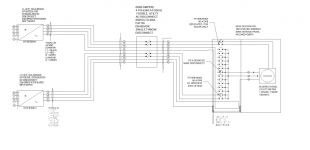
The situation where we are back feeding two SolarEdge 11.4 kw into one siemens Solar ready Main panel TAHT HAS SEPEARTE DEDICATED BREAKER FOR SOLAR INTERCONNECTION.

EXAMPLE
200A MAIN PANEL SIMENS ( MODEL# MC2442S1200SC)
HAS 100A DEDICATED BREAKER SPOTS FOR SOLAR PV ( WE WILL CONNECT 60A HERE)
THEN 60A ( CAN GO IN TO THE MAIN PANEL BUS BAR) After derating it to 175A ( HYPOTHETICAL FOR THIS CASE)
STILL BOTH MAKE 120A OF SOLAR LESS THAN 200A meter socket ratings.

IF THEY REQUIRE SINGLE MEANS OF DISCONNECT WE CAN USE 4 POLE AC DISCONNECT AND DISCONNECT BOTH INVERETR AT SINGLE THROW.

IS THIS ALLOWED THOUGH ?CAN WE USE BOTH SUPPLY SIDE AND LOAD SIDE CONNECTION AT THE SAME MIAN PANEL.
 
It would help our understanding to see a sketch of the proposed situation. From your description, this is what I believe you have in mind. Please correct as needed.
1638848295145.png

If it were my choice, and there were no other factors that governed, I would not recommend segmenting the system. I don't currently see why you couldn't connect it entirely on the line side, but there could be another factor that I'm not seeing. If you did have an opportunity to give input on the main panel, I'd recommend setting up enough headroom on the busbar rating to meet the 120% rule.

Code-wise, I see no issue with segmenting your system into two separate interconnections, as long as they are each code-compliant in their own contexts, and as long as the sum total does not exceed the rating of the service. You might have incentive programs or local/state specific policies that apply, which may not allow this, whether directly or indirectly, but it complies under the NEC. As an example, a program that specifically requires utilty-style meter mounting equipment for production reporting, and multiple meters aren't permitted, as this would govern the decision to aggregate. By contrast, if all that matters about any metering you need is that it be revenue-grade metering in general, it is a simple matter of creatively arranging your wires and CT's to meter both systems with a single metering setup.

Assuming you NEC2014 or later applies, the fact that you have a 100A breaker in excess of the size needed, is no issue regarding the interconnection compliance under 705.12 rules that apply. In this example, 60A + 175A is what governs, and what must not exceed 120% of 200A (i.e. 240A). Inverter 1 is out of the picture of the compliance of inverter 2's interconnection, because no matter what sources supply power to the 175A breaker from its line side, it will still stop the net load at that point from exceeding 175A. Given that you have a breaker in excess of the 60A you need, you would need an OCPD either upstream of the disconnect or integrated within it (hence the fuses), if you wanted it to be 60A as opposed to 100A. The inverter would also require at least one OCPD no greater than the maximum value permitted by the manufacturer, so it could not directly connect to the 100A breaker, and would need a 60A OCPD in the circuit in some form or another.

Likewise, inverter 2 is partially out of the picture of inverter 1's interconnection. The only part of it that is in the picture, is that the amps of both systems add up for compliance with 705.11 (or the equivalent article that applies to line side interconnections in your edition).
 
Last edited:
It would help our understanding to see a sketch of the proposed situation. From your description, this is what I believe you have in mind. Please correct as needed.
View attachment 2558612

If it were my choice, and there were no other factors that governed, I would not recommend segmenting the system. I don't currently see why you couldn't connect it entirely on the line side, but there could be another factor that I'm not seeing. If you did have an opportunity to give input on the main panel, I'd recommend setting up enough headroom on the busbar rating to meet the 120% rule.

Code-wise, I see no issue with segmenting your system into two separate interconnections, as long as they are each code-compliant in their own contexts, and as long as the sum total does not exceed the rating of the service. You might have incentive programs or local/state specific policies that apply, which may not allow this, whether directly or indirectly, but it complies under the NEC. As an example, a program that specifically requires utilty-style meter mounting equipment for production reporting, and multiple meters aren't permitted, as this would govern the decision to aggregate. By contrast, if all that matters about any metering you need is that it be revenue-grade metering in general, it is a simple matter of creatively arranging your wires and CT's to meter both systems with a single metering setup.

Assuming you NEC2014 or later applies, the fact that you have a 100A breaker in excess of the size needed, is no issue regarding the interconnection compliance under 705.12 rules that apply. In this example, 60A + 175A is what governs, and what must not exceed 120% of 200A (i.e. 240A). Inverter 1 is out of the picture of the compliance of inverter 2's interconnection, because no matter what sources supply power to the 175A breaker from its line side, it will still stop the net load at that point from exceeding 175A. Given that you have a breaker in excess of the 60A you need, you would need an OCPD either upstream of the disconnect or integrated within it (hence the fuses), if you wanted it to be 60A as opposed to 100A. The inverter would also require at least one OCPD no greater than the maximum value permitted by the manufacturer, so it could not directly connect to the 100A breaker, and would need a 60A OCPD in the circuit in some form or another.

Likewise, inverter 2 is partially out of the picture of inverter 1's interconnection. The only part of it that is in the picture, is that the amps of both systems add up for compliance with 705.11 (or the equivalent article that applies to line side interconnections in your edition).
Thank you for the explanation yes the SLD is the same as depicted in the picture.
I have added my own just to show the main panel connection with breakers. The main panel is main meter combo so there is no space for CTS, The diagram shows longer wires but in actual main panel it will not have that much space for cts.
we usually used to use square d main panel that has dedicated lugs for line side tap ,but because of material issue its hard to get those panel before hand and I was wondering if we could use siemens panel dedicated for solar and connect both ways.
this project doesnot have battery, doesn't require production meter, We don't need consumption cts connected to the main panel as main meter combo cant do that usually because of limitation of space.
so this resolve my litle doubt I had in my mind if we could connect line and load side at same main panel
Thank you again.
 

Attachments

  • SLD.PNG
    SLD.PNG
    47 KB · Views: 17
Status
Not open for further replies.
Top