Switching Multiple Ballasts with Multiple Single Pole Switches???

Status
Not open for further replies.

mtaylor

Member
Hi,

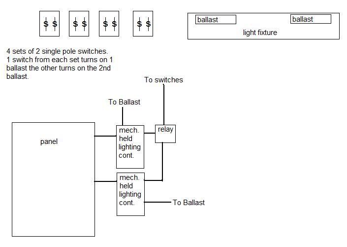
I am trying to figure out how to make this work. The drawings show 4 sets of
double gang single pole switches switching power on for 2 sets of ballasts on each fixture. First of all... will this work at all? Secondly, if so what type of relay, contactor, etc. would be needed to make this work? I would also like to know if it is possible to do this with just one lighting contactor.


mbalmsw.jpg


Thanks!
 
mtaylor said:
That's what I thought. Would be interesting if there was a way to make it work like this though.

You can make it work by using a lo-voltage switches that can turn a relay on & off (similar to residential lo-voltage systems). That relay would in turn control your lighting contactors.

But more than one SP line voltage switch will simply render all the other switches incapable of turning the lights on when one is turned off.

Is there a reason why you need contactors in the first place (ie, so many lights that it's more than one circuit)?
 
480sparky said:
Is there a reason why you need contactors in the first place (ie, so many lights that it's more than one circuit)?

The drawing I showed you is a quick example of the actual set of drawings I have. On the drawings each light fixture has more than 2 ballasts and each switch operates more than a single ballast.
 
mtaylor said:
barbeer said:
Are there 4 separate locations to switch the same lights?
Yes.
Just to clarify, is there (A) a single group of double-ballast fixtures, and you want to control each half of the group from all four locations, or (B) each pair of switches should operate a separate group of double-ballast fixtures?

I'm guessing A, since it should be obvious how to do B.

If the wires are already run, your best bet might be to find relays that switch state with each application of power, and use momentary-contact switches. That's relatively easy.
 
mtaylor said:
The drawing I showed you is a quick example of the actual set of drawings I have. On the drawings each light fixture has more than 2 ballasts and each switch operates more than a single ballast.
You can use a mini logic controller to trigger your lighting contactor(s). I believe they can even be programmed to a flip-flop output for any single change on several inputs... so for instance you have eight SPSW powered with 120V (120V controller) and connected to a controller input. Flip one the switches, the lights go on... flip another switch, the lights go off... doesn't matter whether you are sending 120V or 0V back to the controller because the change in voltage (input high/low) is what triggers the flip-flop output. However, don't forget that single pole switches are marked ON and OFF... and the described operation will not hold true to that... best to use 3-ways for the described type of operation. On the other hand, there can be many other programming options available with this type of control!!!

For example: http://www.meau.com/eprise/main/sit...mmable_Logic_Controllers/Alpha_Series/default
 
Last edited:
What is the purpose of the lighting contactors? If one contactor controls one set of ballasts and the other contactor controls the other set of ballasts then you could use momentary switches from an infinite number of locations.
 
Last edited:
infinity said:
What is the purpose of the lighting controllers? If one controller controls one set of ballasts and the other controller controls the other set of ballasts then you could use momentary switches from an infinite number of locations.
I don't quite understand your question...

When you mention controller(s) are you talking about the type I mentioned: mini-logic controller?
 
Last edited:
Smart $ said:
I don't quite understand your question...

When you mention controller(s) are you talking about the type I mentioned: mini-logic controller?

Actually I meant contactors. His OP mentioned "mechanically held lighting contactors" in his diagram.
 
infinity said:
Actually I meant contactors. His OP mentioned "mechanically held lighting contactors" in his diagram.
Ahhh! That makes more sense :wink:

I think it would be best if the OP'er was specific about the design.
 
Smart $ said:
Ahhh! That makes more sense :wink:

I think it would be best if the OP'er was specific about the design.


I agree, I was trying to interpret his options from the diagram. If each of contactors do indeed control one set of ballasts, momentary switched would be an easy option.
 
Smart $ said:
True... but momentaries aren't a typical wall switch.


Right, but he's asking about single pole switches which won't work at all so he'll need to explore some other type of installation.:rolleyes:
 
infinity said:
Right, but he's asking about single pole switches which won't work at all...
They certainly won't work controlling the contactors directly...

...so he'll need to explore some other type of installation.:rolleyes:
...and thus enter the logic controller. With the exception of single poles being marked ON/OFF they could be made to work. To get away from the ON/OFF markings, change to 3-ways connected for single pole operation, and program the controller for operation of the mechanically held contactors, and good to go (...though there is a learning curve coupled with programming the controller).
 
Smart $ said:
Flip one the switches, the lights go on... flip another switch, the lights go off... doesn't matter whether you are sending 120V or 0V back to the controller because the change in voltage (input high/low) is what triggers the flip-flop output.
That still won't work. You'll still have four paralleled SP switches. The only way to change state is when only one is on at a time. You'd still have to use 3- and 4-way switches.

Now, with momentary switches, as I mentioned earlier, any push would send a pulse.
 
LarryFine said:
That still won't work. You'll still have four paralleled SP switches. The only way to change state is when only one is on at a time. You'd still have to use 3- and 4-way switches.
Not with the logic controller. Each switch would have its own input on the controller. How each switch's position affects the controller output contacts is programmed into the controller. For example, the controller can be programmed such that any one flip of a switch will send a pulse alternately to two output contacts for each bank (i.e. contactor control), one for the latching coil, one for the unlatching coil.

Granted, it may well be a less expensive installation using 3-way and 4-way switches!!!

Now, with momentary switches, as I mentioned earlier, any push would send a pulse.
...and you'd need two momentary switches per bank of lights at each remote-operator location for the mechanically-held relays.

Momentaries (usually a pushbutton-operator type of switch)) are not your typical wall switch and do not provide a familiar operator for building lighting.
 
Smart $ said:
Momentaries (usually a pushbutton-operator type of switch)) are not your typical wall switch and do not provide a familiar operator for building lighting.


We use momentary switches all of the time for lighting controls. Not push button types but standard Leviton Decora momentary rocker switches. They're just a momentary contact, center off, 3-way switch. Press the top for on and the bottom for off.
 
Status
Not open for further replies.
Top