Synchronized clock system question

mark32

Senior Member
Location
Currently in NJ
Hello all,

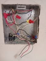
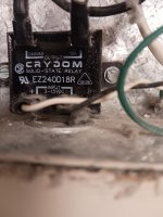
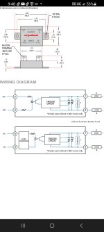
I am trying to troubleshoot this circuit, as the breaker will trip after a few seconds, but I am unsure what I'm supposed to be looking for. In this photo, (Which was taken after we started troubleshooting) you will see the black from the clock's pigtail is together with a lead that goes to that relay. These tie together with the feed (black 120vac) coming in and going out to the rest of the clocks. We are getting continuity to ground on one of the red conductors. (I believe this red conductor is the one that is used to synchronize the clocks). So okay, now we have something to look for. However, what is actually suppose to take place here? I am told 24vdc is applied to the red conductor, (for synchronizing purposes) but how does this occur? You can see some LV wiring on the bottom of the relay, which I assume originates at the master clock two floors above. The relay itself is labeled as such, the "input" is the LV and the "output" are the black and white/red conductors. Initially, I thought once the control wiring closed the relays contacts, 120v would be applied to the white/red conductor, but this is not the case, at least I don't think it is. But, it must be the case, which is why the breaker is tripping. Can anyone shed some light on this for me?
 

Attachments

  • 20250220_114117.jpg
    20250220_114117.jpg
    926.6 KB · Views: 25
  • 20250220_114100.jpg
    20250220_114100.jpg
    808 KB · Views: 27
Last edited:
Is this one of those mechanical clock systems with the hands? The red wire energizes a solenoid that makes all of the clocks advance to 12:00 midnite at the same time. It’s been 35 years since I worked on one of those!
 
I thought once the control wiring closed the relays contacts, 120v would be applied to the white/red conductor, but this is not the case, at least I don't think it is.
Looks to me like when the relay closes 120V is applied to the black conductor. White is neutral, red is hot and black is controlled by the relay.

-Hal
 
Looks to me like when the relay closes 120V is applied to the black conductor. White is neutral, red is hot and black is controlled by the relay.

-Hal
Hi Hal!

I know it's a mess, but if you look close, the neutral doesn't go to the relay. The white conductor, from the relay, ties into the red "Signal" conductors
 
Look at the cable coming into the panel top right marked "feed". White is neutral, black just passes through and red is the hot. The white from the relay connects to the red (hot). The other side of the relay (black) is wirenutted to the black conductor going to the clock Molex connector hanging down.

If you are getting continuity to ground from the red with the breaker off there is a fault either to ground or neutral by the red or you may just be reading the resistance through all the other clocks that go from hot to neutral. Disconnect the neutral of the circuit at the panel and check again. If you still are seeing continuity I'm afraid your only choice is to "divide and conquer". You are going to have to get some idea how the wiring was run, then start removing clocks starting at the end, interrupting the hot passing through then checking the see if the continuity went away. When it does you are getting close.

-Hal
 
Last edited:
Thank you again for your time Hal,

Before leaving the site, we briefly observed a functioning circuit elsewhere in the building. We read 27vdc on the red conductors, how this voltage is introduced to them is what I'd like to understand. Yes, we began to divide and conquer before leaving for the day, I'll be returning today for more troubleshooting. My colleague and I were also thinking that perhaps one of the clocks failed in a way that is creating this short. I was going to begin removing clocks at random, but starting at the end is probably a better idea :) Initially, we thought the relay was bad, so we bypassed it (By removing the white lead on the relay) and the clocks powered up fine, the problem was, they never synched up with the correct time. I will report back later, hopefully with good news :)
 
We read 27vdc on the red conductors, how this voltage is introduced to them is what I'd like to understand.
That makes no sense. If these are 120VAC clocks and they are operating properly how do you measure 27VDC on the power conductors? Did you measure from red to white?

What made you choose this particular clock that you showed us to look at?

-Hal
 
That makes no sense. If these are 120VAC clocks and they are operating properly how do you measure 27VDC on the power conductors? Did you measure from red to white?

What made you choose this particular clock that you showed us to look at?

-Hal
Hello sir!

No one onsite knows exactly how the system works. The only guy that did, passed away a few years ago. I chose this location as it's the only clock, on this circuit, that contains a relay, none of the other associated clocks have one. On a functioning circuit, I read 27vdc from the red to ground with our Fluke T5 - 600. After taking a splice apart on the circuit in question, with the breaker off, I was getting 1.9vdc on my Fluke 117 on the loZ setting. I was scratching my head, but apparently some of the older clocks have small back up batteries in them, so I guess that's what I was reading. Anyway, my co-worker and I traced the short to a section of the building that is currently being renovated :rolleyes: and we couldn't enter the area as the floors were being done. So, we disconnected the mc feeding that section (At a nearby 1900 box) and the breaker held. It turns out the relay in the pic was toasted, because of the current going through it to the short. Luckily, we had purchased an extra one. So we got the clocks back up and running, but I still don't know what is taking place with regards to how the clocks are actually synchronized or what role this relay plays. Thanks again for your time Hal!
 
So we got the clocks back up and running, but I still don't know what is taking place with regards to how the clocks are actually synchronized or what role this relay plays.
Is there a name on the clock face? Simplex maybe? Apparently, that is a 24VDC minute impulse clock system.

Try contacting these guys to see if they can be of any help to you with advice. They can sell you replacement clocks and parts too.


American Time

-Hal
 
Is there a name on the clock face? Simplex maybe? Apparently, that is a 24VDC minute impulse clock system.

Try contacting these guys to see if they can be of any help to you with advice. They can sell you replacement clocks and parts too.


American Time

-Hal
Thank you for the link Hal! Yes, that sure does look like the clocks in question, I'll confirm tomorrow. Full disclosure, this is for a medical building that I am a maintenance electrician for. I've been there for a year now and I really enjoy it! I've been introduced to equipment that I had little to no prior experience with, i.e. generators, fire panel, and now system clocks. Tomorrow I have to troubleshoot some smoke doors that had dropped out today, as the magnets that holds them open are no longer energized, hmm
 
Thank you for the link Hal! Yes, that sure does look like the clocks in question, I'll confirm tomorrow. Full disclosure, this is for a medical building that I am a maintenance electrician for. I've been there for a year now and I really enjoy it! I've been introduced to equipment that I had little to no prior experience with, i.e. generators, fire panel, and now system clocks. Tomorrow I have to troubleshoot some smoke doors that had dropped out today, as the magnets that holds them open are no longer energized, hmm
Power supply failed, or FA relay failed or activated. Could be the magnet, but if double door, only one door would release.
 
At the large 50 year old hospital that I retired from they had a clock control system going to maybe 200 to 300 patient rooms, nurses stations, hallway etc. We had the fuse blow every time zone mechanic replaced it. No drawings or prints. Had one or two guys on each of the six floors disconnecting a # of clocks until we found a shorted clock. In newest building they used a wireless system to control clocks over twelve floors.
 
Top