Coppersmith
Senior Member
- Location
- Tampa, FL, USA
- Occupation
- Electrical Contractor
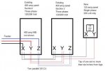
I'm adding a single phase panel right next to an existing three-phase panel that is in two sections. The two sections are connected together with two sets of parallel 3/0 CU. The sections are right next to each other. My panel will be right next to them.
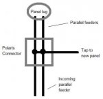
I want to tap one set to power my panel. The tap is going to be very close to the lugs, probably no more than six inches away. I don't think this will unbalance the parallel feeders. What do you think?
I want to tap one set to power my panel. The tap is going to be very close to the lugs, probably no more than six inches away. I don't think this will unbalance the parallel feeders. What do you think?