This Has Me Baffled

Status
Not open for further replies.

Jim M426

Member
Location
SW Florida
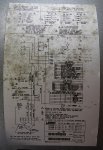
I've got a 240V air handler connected to an outdoor heat pump. I'm looking for the wire that energizes the fan motor when the T-stat calls for it. Should be no big deal, right? Though I spent the bulk of my time in the trade on commercial jobs, I got about 8 years working residential and wired plenty of furnaces and AC units, though no AH/HP units. Still, I've never had any problems reading schematics. But maybe a dozen years in retirement has mushed my brain...

I tested the wiring with the power on but T-stat off. There are 3 wires going to the fan motor. I get 120V to ground on all of them and 0V across any two. I can't find any other wires going to the fan motor other than two ground wires.

On the relay there are 7 spades, one goes to "C" on the 24V terminal, another to "G" on the 24V terminal. All the others read 120V. This is with the fan not running. Somewhere there is an open circuit but I can't find it. Any help?
 

Attachments

  • AH_schematic.jpg
    AH_schematic.jpg
    312 KB · Views: 33
Are you sure all is original? Ours has a harness adapter for a different motor...
Internal thermo protection? I know you are looking down stream...
 
K3 is the relay that switches blower power, it's a 1 pole double throw. Its 24V coil is controlled by the thermostat green lead. Is the fuse in the 24V control circuit good. Is K3 being energized? Is the 24V power on to K3? K3 always has a Normally Closed contact to feed 1/2 the motor winding, hence why you read 120V to ground on all leads even when it's not running. The L2 lead needs to be powered in order to get the motor to start.

You may be lacking the L2 (N) connection to the motor harness, if you read 120V only. The L2 is the other phase leg that powers the blower common lead (240V)
 
On the relay there are 7 spades, one goes to "C" on the 24V terminal, another to "G" on the 24V terminal. All the others read 120V. This is with the fan not running. Somewhere there is an open circuit but I can't find it. Any help?
Are you reading 24V to the equipment ground on both of the "C" and "G" terminals? I believe the "C" terminal should be grounded and measure zero volts to equipment ground.
 
If you’re only getting 120V across all legs on a 240 V compressor, and 0V between them , somewhere in the mix you’ve lost a leg. Could be through a relay or who knows.
 
K3 is the relay that switches blower power, it's a 1 pole double throw. Its 24V coil is controlled by the thermostat green lead. Is the fuse in the 24V control circuit good. Is K3 being energized? Is the 24V power on to K3? K3 always has a Normally Closed contact to feed 1/2 the motor winding, hence why you read 120V to ground on all leads even when it's not running. The L2 lead needs to be powered in order to get the motor to start.

You may be lacking the L2 (N) connection to the motor harness, if you read 120V only. The L2 is the other phase leg that powers the blower common lead (240V)

The AC, AH and fan motor all work fine. What I'm trying to do is wire up a UV/ozone unit to run only when the fan is running.

After I read your post I went back to the schematic. Then it dawned on me, the 120V I get on all three wires at the motor is due to a backfeed through the motor. When I test across 6 & 9 on K3-2, I get 240V. So I just have to wire the UV transformer at 240V across 6 & 9.

At least some rust fell off the old brain.

Thanks all for your help.
 
Status
Not open for further replies.
Top