three phase peak voltage

Status
Not open for further replies.
Snorks said:
Hi Electrofelon,

For AC current; Vpeak = V * Sqrt(2)

True, the peak value of any sinusoid is sqrt(2) times its RMS value. This is true for single phase or polyphase--voltage or current.

Perhaps we don't understand the question?
 
Thanks guys,

Its too late for my brain to explain what its thinking, so until tomorrow, I will just leave this question which might shed some light on where my answer in the OP came from. What would the peak voltage be on the dc side of a three phase full wave rectifier bridge? I think it would be higher than phase voltage*sqrt 2. Am I on to something?
 
What would the peak voltage be on the dc side of a three phase full wave rectifier bridge? I think it would be higher than phase voltage*sqrt 2. Am I on to something?

this is not telling us a lot. in VFDs, frequency is varied so that almost any voltage can be simulated in order to change the speed of a motor.
 
electrofelon said:
What would the peak voltage be on the dc side of a three phase full wave rectifier bridge?

The DC voltage measured at the output of the bridge would be the peak AC phase-phase voltage at the peak of the phase voltage minus the forward voltage drop of the two diodes, so just a tadge less than the peak phase volts..
 
This reminds me of the Fourier Series. That should answer your question. Essentially just plug and chug in the formula.

Vrec = ((2Vac/pi) - (4Vac/pi)) * {sigma(from n=1 to n=3)} (1/(4n^2 - 1))* cos (240*pi*n*t)

the 2Vac/pi is the Dc component, and the rest is the ac component. Vac is the peak voltage at the input to the rectifier.

the ac voltage "decreases" with the first couple of odd harmonics but the frequency increases; the first harmonic gives you a frequency of 120 hz. normally the ac is filtered out with a low pass filter to just pass the DC component.

I hope that helps.
 
Last edited:
A full wave rectifier does not transform the voltage, in the sense that a transformer will transform the voltage. There is no exchange of magnetic fields from the input side to the output side. So the voltage on the output can be no higher than that of the input. And that value is the square root of two times the RMS.

However, the output voltage can be lower than the input. There is some small voltage drop through a pair of diodes, as has been mentioned. But when you say, "full wave rectifier," you are only talking about diodes. So what the output signal will look like is a sine wave for which the negative half has been flipped to the positive side, giving you a series of hills. This thing will have a peak value that is essentially the same as the input wave, and essentially the same RMS value as well. That is because of the "S" word in "RMS." When you square the negative half of a sine wave, you get a positive number, so the rest of the math is the same for the original and the full-wave rectified signals.
 
Sorry, you are correct, the voltage decreases, the frequency increases.
Typing before thinking again.

(this early morning engineering is for the birds)
 
charlie b said:
...So what the output signal will look like is a sine wave for which the negative half has been flipped to the positive side, giving you a series of hills.
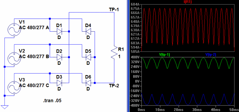
That depends on the voltage reference. If the voltage reference is the 3? system neutral, the output of a full-wave rectifier will be out-of-phase positive "hills" and negative "valleys" at 180Hz.

If the output voltage is just measured across the output, it will be as you have said with the AC component at 360Hz.

peakvoltage1.gif
 
Ok I see what I was doing wrong - my .8165 figure will give the peak voltage from phase to neutral, when multiplied by phase to phase rms. Example: 240 rms phase to phase, 240*.8165=196 which is peak voltage phase to neutral (yes i know, a 240 wye would be strange). Anyway this is what I was thinking the peak after rectification would be becuase I was erroneously assuming the neutral was my reference point on the dc side but of course it is not - its another phase. Its a bit confusing the way they pictoralize the waveforms before and after rectification, it makes it easy to think the neutral is you reference and rectification allows you to 'keep' the peaks (196v in the above example). The correct answer is 240*1.414 - about .6 volts dropped through the rectifier for a total of a bit under 339.
 
Yup!

Yup!

Smart $ said:
That depends on the voltage reference. If the voltage reference is the 3? system neutral, the output of a full-wave rectifier will be out-of-phase positive "hills" and negative "valleys" at 180Hz.

If the output voltage is just measured across the output, it will be as you have said with the AC component at 360Hz.

peakvoltage1.gif

If we use ideal rectifiers, the peak voltage across the load, in this case, will be,

Vpkload = 480Vrms x sqrt(2) = 679V

Can't get away from sqrt(2)!
 
rattus said:
If we use ideal rectifiers, the peak voltage across the load, in this case, will be,

Vpkload = 480Vrms x sqrt(2) = 679V

Can't get away from sqrt(2)!
Is there a reason you quoted my post? I was discussing waveform. How did we get back to calculations?
 
Smart $ said:
Is there a reason you quoted my post? I was discussing waveform. How did we get back to calculations?
Yes, your diagram illustrates my point. Although peak voltage may be a misnomer here.
 
Status
Not open for further replies.
Top