Three way switch troubleshooting

Status
Not open for further replies.

Pharon

Senior Member
Location
MA
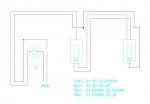
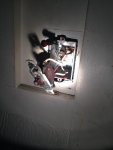
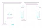
So aside from the obvious (and easily correctable) 404.2(A) violation, what could possibly be going on here? How can there be a voltage drop differential simply by changing the position of a switch? I also can't help but wonder if it's more than a coincidence that one of the four scenarios is 2/3 line voltage and the other two are about 1/3 line voltage. Can a bad switch create a voltage divider like this? Or is it only possible by having an unknown load being tapped somewhere else in the circuit?

I plan to get two new replacement 3-way switches tomorrow and re-test, but thought I'd throw this out there to see if I'm missing something obvious.

(The magenta wire is actually white, just changing it for pic clarity)
 

Attachments

  • 3 way.jpg
    3 way.jpg
    57.8 KB · Views: 1
1. If you are really measuring the voltage with a high impedance meter on an empty receptacle, it is likely that three of your four voltages are just capacitive leakage voltages. Try plugging load in and repeat the measurements.
2. Given that, it is likely that either one of the switches is bad or one of the travelers is open. It might also be a miswiring at one or both switches.
 
Ground fault on EMT with a bad connector and no green in the pipe.

Sorry, couldn't resist.

Without some more information it is hard to say but I would agree with Goldy, if a digital meter is involved you can get readings like you have shown.

I have also troubleshot three ways and the switches test out fine one time but then showed up as the source of an intermittent problem later, so changing them is a good idea.
 
As long as you're going to be removing the 3-ways, test for proper voltage with the switches removed. Also splice the wires through and see if the voltage is the same at the other end. If so, then my guess is that the switches might be back-lit and you're reading through the neon bulb in one or both of the switches. My second guess would be that you might be on a GFI circuit that is not working properly. I recently had a similar situation in a residential garage with similar voltage readings. Found a GFI receptacle with a transformer plugged into it. The GFI had tripped but the Xfmr would not allow the tripped button to fully extend.
 
I am sure you have noticed the wiring is not correct. IMO if you correct the 3way wiring you will be OK.

as it is you are not reading a voltage across hot and neutral.
 
Ground fault on EMT with a bad connector and no green in the pipe.

Sorry, couldn't resist.
LOL - all of the wiring is 1950s cloth style romex with ground, either 14/2 or 14/3. Readings from hot to metal box read 124V.

Without some more information it is hard to say but I would agree with Goldy, if a digital meter is involved you can get readings like you have shown.
Yeah, I didn't think about the phantom voltage readings you can get with no load. I was considering plugging in an incandescent lamp into one of the two receptacles (it's actually a duplex) and testing the other one, and seeing if I still get the same voltage drop readings (before I change anything). Just to see if they're real.

As long as you're going to be removing the 3-ways, test for proper voltage with the switches removed. Also splice the wires through and see if the voltage is the same at the other end. If so, then my guess is that the switches might be back-lit and you're reading through the neon bulb in one or both of the switches. My second guess would be that you might be on a GFI circuit that is not working properly. I recently had a similar situation in a residential garage with similar voltage readings. Found a GFI receptacle with a transformer plugged into it. The GFI had tripped but the Xfmr would not allow the tripped button to fully extend.
Good suggestion about removing the 3-ways and splicing - I think I will do that, just to make sure it's continuous. These 3-ways are not back lit - they're old (see attached pic), and there is no GFI in the circuit.

Is a dimmer involved?
No.

I am sure you have noticed the wiring is not correct. IMO if you correct the 3way wiring you will be OK.

as it is you are not reading a voltage across hot and neutral.
Yes, I mentioned in my first post that it's a 404.2(A) violation. As it's the neutral that's being switched instead of the hot, the voltage readings I'm taking are from hot to neutral -- but through both switches.

One thing I'm worried about, though, is that if I change it from switched-neutral to switched-hot, and that somewhere elsewhere in the circuit they bugged off of that switch path, I could end up getting 240V (or 0V) at an outlet. But I plan to disconnect all loads from this circuit before trying that.

Thank you all for your input. I greatly appreciate it.
 

Attachments

  • 2014-09-07 17.58.26.jpg
    2014-09-07 17.58.26.jpg
    142.7 KB · Views: 1
That hookup is not compliant any more but that has nothing to do with the problem.

200.7(C) Circuits of 50 Volts or More. The use of insulation
that is white or gray or that has three continuous white
stripes for other than a grounded conductor for circuits of
50 volts or more shall be permitted only as in (1) and (2).
(1) If part of a cable assembly that has the insulation permanently
reidentified to indicate its use as an ungrounded
conductor by marking tape, painting, or other
effective means at its termination and at each location
where the conductor is visible and accessible. Identification
shall encircle the insulation and shall be a color
other than white, gray, or green. If used for single-pole,
3-way or 4-way switch loops, the reidentified conductor
with white or gray insulation or three continuous
white stripes shall be used only for the supply to the
switch, but not as a return conductor from the switch to
the outlet.
 
I'm confused -- so is it saying that even if I re-identify the white conductors with black tape (after I swap it from neutral-switch to hot-switch), it's still not compliant? That last sentence seems to say so. Or am I reading it wrong?

I would think it's also not compliant anymore because there would be no neutral present at either switch box.


You cannot use the white wire as the return to the light. It looks like that is what you have. I am guessing the 2 wire cable in the box is a switch loop.
 
You cannot use the white wire as the return to the light. It looks like that is what you have. I am guessing the 2 wire cable in the box is a switch loop.
Yes, I believe it is. And to make it compliant, the (relabeled) wiring should be re-done to look like the attached. Good catch.

I also added dashed lines to indicate where the sheaths come into each box.
 

Attachments

  • switch new.jpg
    switch new.jpg
    48.3 KB · Views: 0
When I get readings like this, I grab my solenoid tester, aka Wiggy. I still carry it just for these types of situations.
Why? Would a wiggy not beep on those 81V and 58V readings if they were just phantom? Is that what you're saying? I hadn't considered that.
 
Why? Would a wiggy not beep on those 81V and 58V readings if they were just phantom? Is that what you're saying? I hadn't considered that.

A solenoid tester puts an actual load on the wire. The more voltage, the higher up the scale it moves. It does not read induced voltages.
 
Have you confirmed that you have correctly identified the common pole terminal of the switches?
Sometimes it is not as obvious as the terminal farthest from the other two being the common. (The way you drew them.)
It is just as likely that the single terminal on one side of the switch is the common and the two terminals on the opposite side are the DT poles.
Just buzz the switches out with an ohmmeter (after disconnecting, of course.)
 
Last edited:
Have you confirmed that you have correctly identified the common pole terminal of the switches?
Sometimes it is not as obvious as the terminal farthest from the other two being the common.
Just buzz the switches out with an ohmmeter (after disconnecting, of course.)
Funny you should mention that -- a friend of mine said the exact same thing and I told him he was being ridiculous. :)

But you're both right -- and I will do just that. Who knows with switches this old...
 
This is in my house. And no, they have never worked right. I didn't realize it wasn't a single pole switch until I opened the box and saw the travelers. By process of elimination I found the other switch that I thought was broken but controlled outside lighting. In retrospect, it should have been obvious.
 
Why? Would a wiggy not beep on those 81V and 58V readings if they were just phantom? Is that what you're saying? I hadn't considered that.

The capacitively coupled "source" giving you those 81 and 58 volt readings is not stout enough to deliver enough current to a low impedance meter (which a wiggy is low impedance when it comes to voltage measurement devices). In effect the low impedance measuring device is shorting out the source of the 81 or 58 volts. The "capacitor" storing this voltage is the combination of conductor, some insulation and another conductor, it is a very weak capacitor but is still effectively a capacitor.
 
General voltage drop

General voltage drop

It could be that there is a general voltage drop among circuits that are improperly sharing neutrals. Test by seperating splices in various locations where more than one circuit is spliced. If you have a circuit with multiple neutrals, put them in order and voltage will balance.
Is a dimmer involved?
 
Status
Not open for further replies.
Top