Top App contest - Buck/boost question

Status
Not open for further replies.

crossman

Senior Member
Location
Southeast Texas
We held our 5-state top apprentice contest last weekend. The buck-boost question went something like this:

Given:

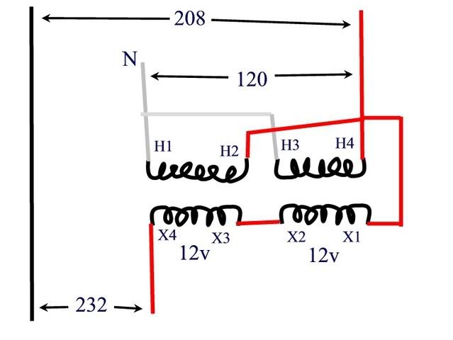
208Y/120 3-phase, 4-wire system
Standard single-phase 120/240 - 12/24 buck-boost xfmr

Problem:

Derive a single-phase circuit of AT LEAST 230 volts and no greater than 240 volts. (In other words, 229.9 volts doesn't cut it).

***EDIT: Further info from "the Judges" has pointed out that the output voltage needs to be greater than 230v but less than 235v. Sorry, for misleading you.***

I was not a participant or judge, I was simply an interested bystander. After the contest was over, I was given the problem and the solution. However, it is my thought that the solution was incorrect and that the given problem does not have a solution.

Anyone care to give it a shot before I post the supposed "solution"?
 
Last edited:
Let me guess: place the primaries in series, apply 120v to a single primary winding, and take 240v out.

In other words, use the two primaries as a 1:2 step-up autotransformer. The secondary wires are not used.
 
LarryFine said:
Let me guess: place the primaries in series, apply 120v to a single primary winding, and take 240v out.
:D LOL :D

I'll take the copper from that "scrap" secondary. :)
 
I can get 231.1V, using both primary and secondary coils in a buck/boost configuration.

I also see how to get 229.9V. Hint: the 231.1V connection is _very_ similar to the 229.9V one.

But I like Larry's solution better.

-Jon
 
LarryFine said:
Let me guess: place the primaries in series, apply 120v to a single primary winding, and take 240v out.

Larry, that is a beautiful and elegant solution. I like it.

When I presented your solution to "those in the know", they informed me that I had misrepresented the question. The output voltage is required to be between 230 volts and 235 volts. Sorry, my mistake. But I really do like your solution.

so can we get between 230v and 235v?
 
winnie said:
I can get 231.1V, using both primary and secondary coils in a buck/boost configuration.

I also see how to get 229.9V. Hint: the 231.1V connection is _very_ similar to the 229.9V one.

The only thing I can see to get close to 230v would be 228.4v. I see no way to get close to but not less than 230v.

Jon, any diagrams?
 
Smart$:

Thanks for the response. In the first diagram, I am seeing 228.8 volts, which is close enough to 230 for the real world, but barely misses being the proper solution to the problem.

The second diagram, let me think on it for a bit. I don't see us getting 240 from that. Anyone have any explanation of what is going on in the second diagram? Me and a co-worker looked at that earlier, and I think I see the theory, but something just isn't jiving for me.
 
crossman said:
Smart$:

Thanks for the response. In the first diagram, I am seeing 228.8 volts, which is close enough to 230 for the real world, but barely misses being the proper solution to the problem.

The second diagram, let me think on it for a bit. I don't see us getting 240 from that. Anyone have any explanation of what is going on in the second diagram? Me and a co-worker looked at that earlier, and I think I see the theory, but something just isn't jiving for me.

It makes no difference wht the manufacturer's marketing literature says. given a 120x240 input and 12x24 output the possible voltage ratios are fixed by physics.
 
jim dungar said:
It makes no difference wht the manufacturer's marketing literature says. given a 120x240 input and 12x24 output the possible voltage ratios are fixed by physics.

I agree completely Jim, but I am not sure what your point is.
 
crossman said:
The only thing I can see to get close to 230v would be 228.4v. I see no way to get close to but not less than 230v.

Jon, any diagrams?

See diagram SP-6 that Smart $ posted.

Notice how the low voltage coils are connected with reverse polarity relative to the high voltage coils. If line and load were reversed, this would be a buck configuration.

The transformer works in either direction; a 'reversed buck' works just fine.

With a 120/240:12/24 transformer, the ratio as a buck would be 240:216; so with a 208V input you get 231.1V. If you had a 120/240:16/32 transformer, then you could get 240V.

-Jon
 
wouldn't these phases only be 120 degrees apart? Is that a part of the question that is to be ignored?

I guess the only answer I can think of is to tie one primary to both of the secondaries for 232 volts. 208 plus 24

edit: the part of this I am wondering about is if the other secondary would have the ability to boost the current without its primary being fed.
 
Last edited:
danickstr said:
I guess the only answer I can think of is to tie one primary to both of the secondaries for 232 volts. 208 plus 24
Only one problem with that: 208v into a 240v primary gives you 20.8v from a 24v secondary.

That's where everyone was getting the 228.8v, and why they make 120/240-to-16/32v units.
 
ugh. right. According to the Dongan PDF's that diagram SP-6 is actually for 216 to 240, so it may very well do the job, when fed by 208, the boost would be close to 231
 
danickstr said:
ugh. right. According to the Dongan PDF's that diagram SP-6 is actually for 216 to 240, so it may very well do the job, when fed by 208, the boost would be close to 231
Diagram SP-6 is not limited to 216 to 240. Look at the second page for type Y xfmrs, at the bottom of of the 208 to 240 column.

That is the thing about buck-boost transformers... the output voltage will vary with the loading of it. No load condition was set in the OP problem. While Jim Dungar is basically correct in his post above regarding the physics of it, I disagree with his comment about manufacturer's literature, because loading must be take into account for a specific output voltage.
 
Here is the answer from the contest. I have an issue with it. They are using the 120 volt phase to neutral to put 120 on the BB xfmr, giving 12 v at each secondary. Series this gives a 24 volt boost. Then they take that to the other phase conductor and 208 + 24 = 232.

bb.jpg


Problem to me is that the 24 volt boost is not in phase with the 208 volt, so they do not add up, they must be added vectorially. And this comes out to less than 230 volts.

As for the second diagram SP-6 posted on the first page, I will look into that further. Looks good, but I am still thinking about it, gotta understand what is going on.
 
Last edited:
Okay, that was easy enough. Diagram SP-6 could start with 230 volts and buck it to 207 volts. Makes since that if we feed it "backwards" with 208, then we will get slightly above 230v.

Cool for me.
 
Status
Not open for further replies.
Top