D!NNy
Senior Member
- Location
- San Luis Obispo
| Hello, I am copying this data from SKM website: someone please help me to understand why there is curve shift for only a single phase to ground fault of Delta Wye Grounded configuration which is 0.58% where as line line fault current is 0.5pu on the primary side. I understand the explanation provided below that primary relay is seeing fault current of 1.0pu on at least one of the phases which a relay can trip the circuit breaker (assuming that there is no single phase tripping) except in the case of single phase to ground fault shown My question if there is a line line (Phase A and C as shown in the table) fault on secondary side of a 12kV to 480V 3X100kVA pole mounted transformer Delta Y grounded configuration, protected by the fuses on the primary side (individually operated). in this case fuses on the phase A and C has to be sized for 0.5pu transformer curve shift and phase C as 0.58pu. OR curve shift to applied 0.5pu for all phases and coordinate the fuses properly. Am i doing correct?? Thanks for the suggestions Have a great day. | ||
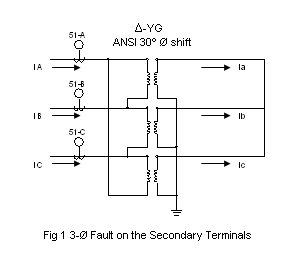
| Through-Fault Current Protection Engineers must consider all possible fault scenarios on the secondary-side of the transformer in order to evaluate the level of through-fault current protection provided by a primary-side fuse, relay or circuit breaker. On a three-phase power system this would include; three-phase fault, single-line-to-ground fault, line-to-line fault and line-to-line-to-ground fault. It is common practice to view current distributions in per unit on the three-phase fault current base seen by the primary-side protective device. Three-Phase (3?) Secondary Fault The primary-side relays would each see 1.0 A p.u. fault current on a 3-? primary fault current base, figure 1. | ||
| ||
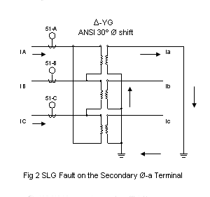
| Single-Line-to-Ground (SLG) Secondary Fault The primary-side phase A and C relays would see 0.58 A p.u. fault current on a 3-? primary fault current base, figure 2. | ||
| ||
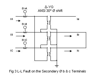
| Line-to-Line (LL) Secondary Fault The primary-side phase A and C relays would see 0.50 A p.u. fault current and the phase B relay would see 1.0 A p.u. fault current on a 3-? primary fault current base, figure 3. | ||
| ||
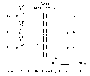
| Line-to-Line-Ground (LLG) Secondary Fault The primary-side phase A and C relays would see 0.58 A p.u. fault current and the phase B relay would see 1.0 A p.u. fault current on a 3-? primary fault current base, figure 4. | ||
| ||
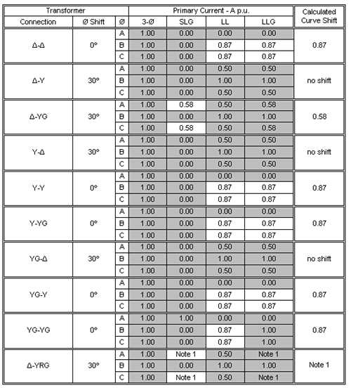
| Transformer secondaries were faulted and primary currents were calculated for each fault type and summarized in Table 2 for winding configurations listed in Table 1. | ||
| Table 2 Fault Current Summary Table | ||
| ||
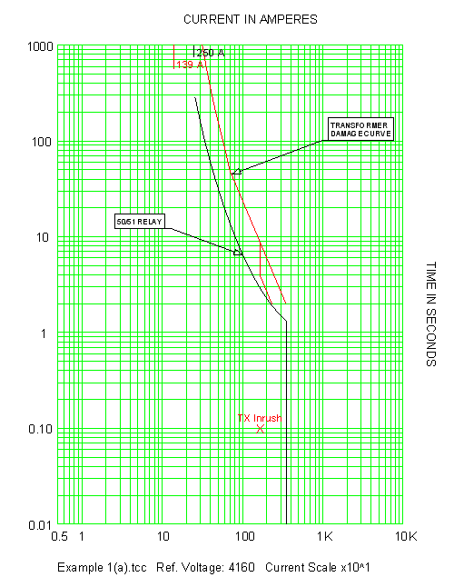
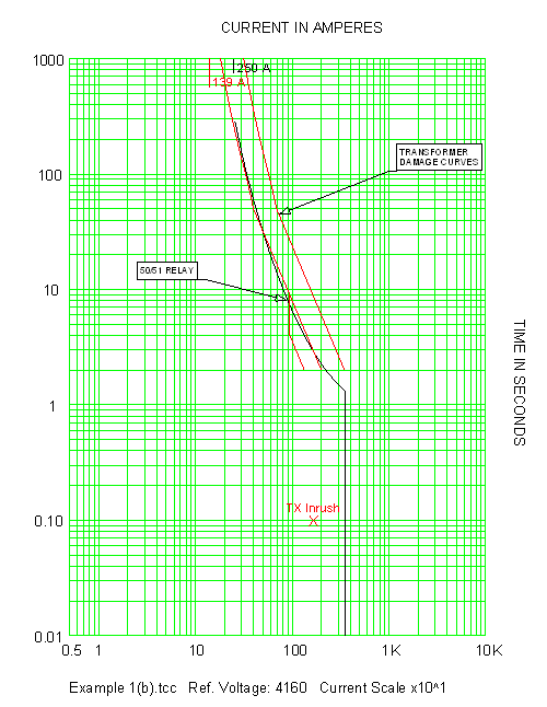
| 1. Shifting of the damage curve is dependent upon the amp rating of the NGR relative to the transformer primary-side FLA. Shifting is To Be Determined by the engineer on a case by case basis. For a sample case study see Example 3. Example 1 Plot the damage curve and set a primary-side 50/51 relay to protect a 1000kVA, 65?C, 4160-480/277V, ?-YG, oil-filled, substation transformer with an impedance of 6.0%. Consider secondary 3-? faults only when setting the primary-side 50/51 relay to protect the transformer during through-faults. Solution The protection is met based on the criteria given, see Figure 5. Now examine the protection provided by the 50/51 relay shown in figure 1 for faults of all types using Table 1. For a secondary LL fault the primary relays in phases A and C would only see 50% of the fault current they would otherwise see for a 3-? fault. This is not a problem though because the B-phase relay would see 100% current, and the transformer would be protected. The LLG fault is similar to the LL fault accept that the relays in phases A and C would see 58% current. But again the B-phase relay would see 100% current, so the transformer would be protected. However for the SLG fault case, the A and C-phase relays would see 58% current with no current flowing in the B-phase! In order to evaluate the through-fault current protection afforded by the relays for a secondary SLG fault, the damage curve of Figure 5 would have to be shifted 58% to the left. It is common practice to show both damage curves on the TCC. After shifting it becomes apparent that the original relay settings are inadequate, see Figure 6. Example 2 Repeat Example 1 but now consider secondary faults of all types when setting the primary-side 50/51 relay to protect the transformer during through-faults. Solution The protection is met based on the criteria given, see Figure 7. | ||
| ||
| Fig. 5 Example 1 Though-Fault Current Protection (3-? Fault Only) | ||
|
