Transformer taps to adjust output volts

Status
Not open for further replies.

Jpflex

Electrician big leagues
Location
Victorville
Occupation
Electrician commercial and residential
Yesterday I posted about my coworker who wanted to feed a single phase panel’s A phase from a 30KVA 480 volt delta primary / 208Y-120 volt secondary output x1 terminal, then panels neutral fed from transformers x2 and finally panels B phase from the transformers secondary output x3 terminal

This was obviously wrong. He finally listened to me and replaced the single phase panel with a 3 phase panel.

However, the fixed machine he was trying to power up required 3 phase 240 volts but output on standard transformer taps provided around 208 volts phase to phase as expected and the machine would not run

My question is that while my coworker did not want to change the transformer to a 480/240 volt separately derived system and although I knew I could boost the output voltage by changing the taps to the max output setting (as if the incoming voltage was lower than nominal), the input voltage was on the high end 509 volts due to utility substation.

Although I did not like using this method I was able to get output voltage to the target 240/120 volts out from this 30KVA 480 delta/ 208Y-120 transformer

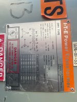
My concern is that as shown in the transformer label, this max tap setting is available if incoming voltage was on the low side 432 volts. Therefore, would doing this as a cheap way to boost voltage harm the transformer which were meant to see a lower primary voltage under this tap setting?
 

Attachments

  • IMG_1420.jpeg
    IMG_1420.jpeg
    111.9 KB · Views: 17
Although I did not like using this method I was able to get output voltage to the target 240/120 volts out from this 30KVA 480 delta/ 208Y-120 transformer
Since you have a Wye secondary the output voltage would be 240/139 volts. Not sure if the 139 matters for what you're doing.
 
Changing the taps as you describe (using the 432V tap supplied with 504V) will operate the transformer at higher than its designed volts/turn.

This will increase magnetic saturation and core loss, and might result in a distorted output waveform. The transformer will have greater inrush current when being energized. The transformer will run hotter and will have reduced life.

This may or actually be a problem, depending upon how much 'headroom ' was originally designed into the transformer.

Jon
 
This is what I thought. Kind of like applying 240 volts to a 120 volt motor and over saturating the windings and finally blowing them open.

So the taps should only be used according to the actual input voltage from the separately derived system upstream and not try to increase output by using a higher output tap with higher rated input voltage?

I guess just because something can be done and will work for a short while doesn’t mean it should be done.

So was I right in recommending a different transformer? My coworker kinda gave me a ridicule just because I told him we needed another transformer but still apparently got the system working without
 
By the way w
Changing the taps as you describe (using the 432V tap supplied with 504V) will operate the transformer at higher than its designed volts/turn.

This will increase magnetic saturation and core loss, and might result in a distorted output waveform. The transformer will have greater inrush current when being energized. The transformer will run hotter and will have reduced life.

This may or actually be a problem, depending upon how much 'headroom ' was originally designed into the transformer.

Jon
hat does the BIL hv 10 KVA and lv 10kva mean on the nameplate shown?
 
This is what I thought. Kind of like applying 240 volts to a 120 volt motor and over saturating the windings and finally blowing them open.
...

So was I right in recommending a different transformer? My coworker kinda gave me a ridicule just because I told him we needed another transformer but still apparently got the system working without

I think you are right, with caveats.

The analogy is closer to running a 208V motor at 240V. You _will_ see more saturation and core loss.

I overstated when I said you will see reduced life. Heating from load current also plays a part, as well as ambient conditions. In other words, what matters for the life of the transformer is the total winding temperature, and by using it at excessive input voltage you are turning up the knob on one of the heat input terms.

You are on the part of the map that says 'here be dragons' . The transformer is being operated well out of spec, and might last a while or might not. It _will_ have a shorter life than similar current usage at the proper voltage, but that might mean 10 years rather than 80. The installation is arguably a code violation (installation not in accordance with manufacturer instructions).

I think you are right to be uncomfortable with this installation, but keep in mind that the factors which make it wrong are more grey area or random in nature, so you might see the unit function for a good long while....or you might see a failure tomorrow.

Jon
I did change the transformer taps to mid range today single the machine actually needs 220 volts 3 phase instead of 240 volts, and dropped output a little but not enough yet

I was also getting 132 volts for lighting and receptacle loads before changing taps. We are still in the high side so I’ll have to change taps a few steps tomorrow to lower transformer output voltage and retry

My coworker cut out the “guts” panel from another 3 phase panel that was too large. He cut the guts half way and placed it into another cabinet that was too shallow to shut a cabinet door

We ran xo from the transformer to this Frankenstein cabinet and derived neutral buss all bonded together as first point of disconnect (Frankenstein cabinet) for this new separately derived system.

We were able to power single phase loads, lights and receptacles from any single breaker (1 phase) and derived x0 neutral bonded to cabinet and neutral buss to get 132 volts.

As I explained I would lower taps to target 120 volts tomorrow. Coworker has not yet connected a 3 phase main breaker in cabinet nor installed a ground rod for system yet

I’m aware that the proper way to do this would be to change the transformer 240/120 single phase using 2 legs from 3 phase supply and terminating secondary to feed a single phase panel but company only judges whether a system is working to power equipment and is either not knowledgeable of code or is nonchalant.
 
Status
Not open for further replies.
Top