transformer taps

Status
Not open for further replies.
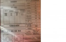
Is there any reason I cant achieve 2.5% taps on this transformer? Say for example getting 2460 by connecting 1&3? Clearly they dont show that as an option

Connecting 1 and 3 will short across a portion of the primary winding and cause a significant current to flow through it.
If you connect either 3&2 or 1&4 you will have the proper volts per turn for a 2460V input, but the voltage across the two secondary windings will differ by 5%.
 
Sorry, 1&3 was a typo, meant 1&4. Thats is what I am not clear on, is the physical construction of the transformer and whether "symmetry" matters. You are saying it does for split phase operation? So it wouldnt matter for straight 240 connection?
 
I have to think about it more, but I think there would be a volts-per-turn difference with an asymmetrical connection, causing, you guessed it, overheating.
 
For straight 240 connection it would not matter(I dont think). It would only mater for connection to your grounded conductor that would no longer be a neutral.

Edit:I'm curious what others might say that have done it.
 
Looking at it again, I believe that the voltage on the two secondary windings should still be reasonably balanced because all of the windings are on a common core. The schematic can be somewhat misleading if you don't keep that in mind. Depending on the physical construction, there might be a slight difference in the impedance presented at the output of the two secondary windings, but I don't think that would matter in most cases.
However, connecting 3&2 or 1&4 will depart from the manufacturers directions and all that may entail, which I will leave to the experts in that area. :)
 
If the secondary windings are put in parallel to get 120V, then a slight difference in impedance at the two secondary windings (as mentioned above) might impact on how well they share the load current. It's probably best to maintain as much symmetry as possible when you are paralleling anything. For 120/240V split phase or 240V 2-wire I don't think there will be an issue.
 
Last edited:
Thanks for the thoughts. I remembered I have the winding diagram for another similar unit. FWIW, this one does allow the "asymmetrical" connections.
 

Attachments

  • DOC101416-10142016080834.pdf
    26.6 KB · Views: 8
I have to think about it more, but I think there would be a volts-per-turn difference with an asymmetrical connection, causing, you guessed it, overheating.
With only two conductors on the primary, there is only one primary voltage, so it's not possible to have a volts per turn difference. I.e. the voltage of the tap point would just move away from the midpoint of H1 and H2 as required.

Cheers, Wayne
 
With only two conductors on the primary, there is only one primary voltage, so it's not possible to have a volts per turn difference. I.e. the voltage of the tap point would just move away from the midpoint of H1 and H2 as required.

Cheers, Wayne
I agree, as long as it is only two wire input, you should be able to make any connections possible between the taps near mid point, the label just happens to only show limited amount of possibilities.

Seen more possibilities on labels with similar arrangement before, though they were typically 480 x 120/240 transformers and not 2400 volt primary.
 
Don’t know why not.
all your doing is shortening or lengthening the one primary coil.
 
Status
Not open for further replies.
Top