Trig for trades

Status
Not open for further replies.

RETRAINDAILY

Senior Member
Location
PHX, arizona
I'm kicking 90's to the wall and the way I figured it :roll:

1st pipe 1" kick =3 deg at 19.120"
2nd pipe 3.5 kick =10 deg @ 20.161 deg
3rd pipe 6" kick =17 deg @ 20.519"

and so on

to have all the kicks to match.
 

dicklaxt

Senior Member
I'm not a guy for math,,,,,,,,,,what I would do is put a LB at the bottom roll it to match up with a rolled 90 from the top,add cplgs and nipples for allignment/makeup or unions and nipples.

I'm not sure but wouldn't the cost of additional material be less than the time spent to bend all those kicks,just a thought.........

Amother question are you transitioning from a level run to a higher level run or a level to a vertical run.

dick
 

cadpoint

Senior Member
Location
Durham, NC
Opposite angle / Adjacent angle = Tangent length

Cos angle = A/H < I always try to use this one and precludes to the following:
or
Sin Angle = O/H

You need two angles and one length, or two lengths and one angle(but that's another equation), for this simple proof'n... OK I think I got that Right, Duh...

But still the minimum to use this "equation".

I'm not sure your math is correct in the picture, or your second post; IE, Upper left Quad of detail.

But the real problem is all the conduits are coming from the same point, they can't occupy that same point, the points of each conduit have to change with some spacing to the wall, as well. Point is that its a flat set of conduits on the ground transitions to a wall in vertical.

You show all conduits from one point, If my logic thought is still prevailing... ;)
 
Last edited:

RETRAINDAILY

Senior Member
Location
PHX, arizona
The 90's are stubbed down spaced at 2"on the down and 2.5 on the rack so i just need to spin on a kick


I started with O and A
then O/A=T
then converted TAN. to sin.
then O/S=H


too get Deg. and Hypotenuse

it was probably the long way But I think I can check my self with O/H=s
 

cadpoint

Senior Member
Location
Durham, NC
Let me throw this out and to remember what your looking at and it will hit you later....

I can remember it to relate to Sin; and use "Oh".. or Sine (OF) = opposite angle OR sin|sine. S=O/H

And C an A due to the letters in my last name; COS (OF) = Adjacent angle.

(my name) Ca... C=A/H

OR U cos when you sin son :) Go Navy
 
Last edited:

Smart $

Esteemed Member
Location
Ohio
I'm kicking 90's to the wall and the way I figured it :roll:

1st pipe 1" kick =3 deg at 19.120"
2nd pipe 3.5 kick =10 deg @ 20.161 deg
3rd pipe 6" kick =17 deg @ 20.519"

and so on

to have all the kicks to match.
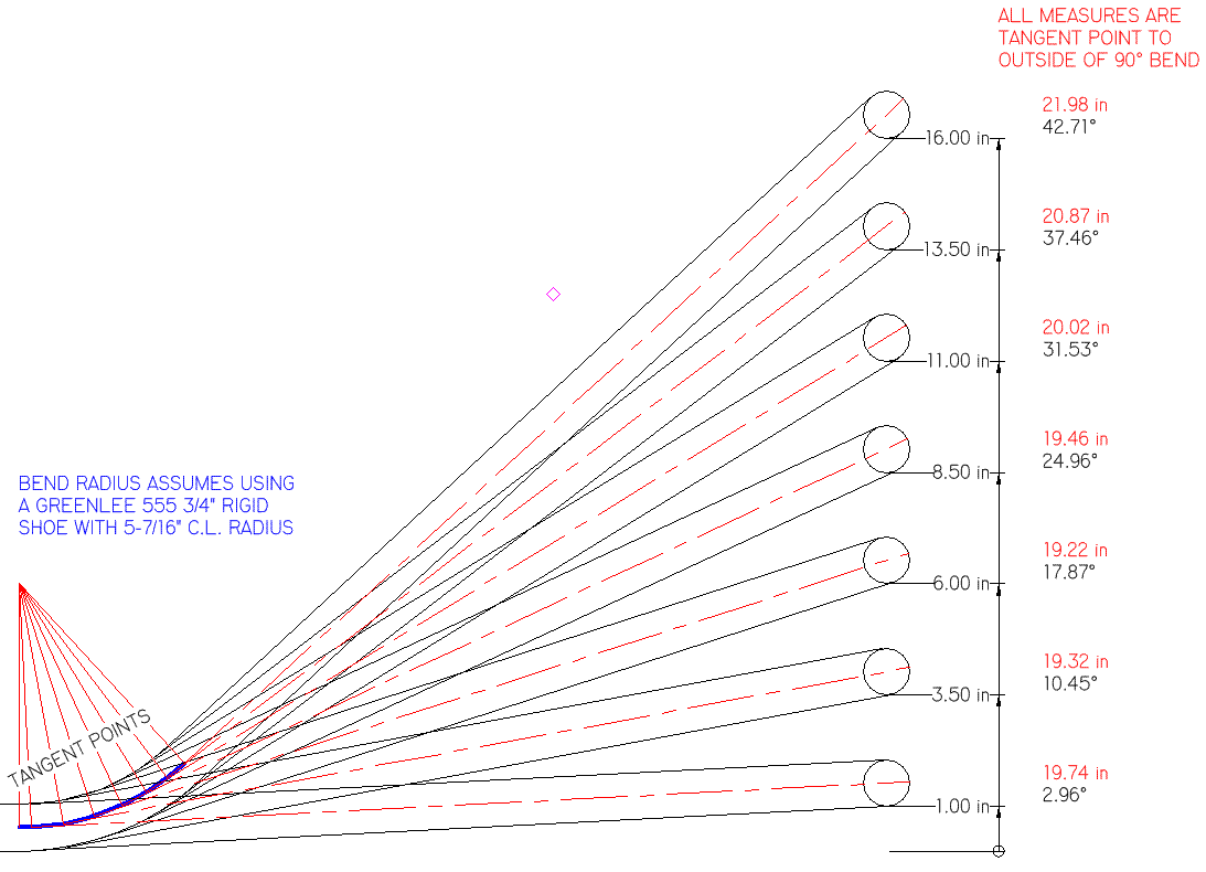
The thing about doing it this way, you have to account for the conduit (or the gain, depending on how measured) in the kick bend. I drew it up in TurboCAD...

TRIGFORTRADES.gif
 

RETRAINDAILY

Senior Member
Location
PHX, arizona
The thing about doing it this way, you have to account for the conduit (or the gain, depending on how measured) in the kick bend.

Thats what I'll be doing tomorow
I seem to be off on my figuring :confused:

Thanks for the dwg.
I'll print that out and take it with me Mon. and get pic when its done.:grin:
 

RETRAINDAILY

Senior Member
Location
PHX, arizona
The thing about doing it this way, you have to account for the conduit (or the gain, depending on how measured) in the kick bend. I drew it up in TurboCAD...


I see what you mean now :) I'll have to play with your numbers and see where the gain comes from It looks like Adjacent Side.

I was thinking Shrinkage of the length of the pipe
 

cadpoint

Senior Member
Location
Durham, NC
Is Smart?s picture exactly what your doing? I think we can all play along if this is the case!

But I didn?t do any math and I don?t have any tables of the 5-7/16? shoe bender.

What?s bothering me is the fact of where the tangent points are set up in Smart?s Drawing. That point is set on the center of the conduit.

I believe and I might be totally wrong but will stick my neck out to say that the tangent points should be set to the bottom of the conduit. Yes I realize that that certain measurements need to be met, But math wise you can?t rationally use the sine/Cos equation, one has to use the bottom and not the center of conduit to get past the 1?, 3.5?, etc increments, as the drawing is presented, or as your trying to apply the offset and the sine|cos equations?

Or to say another way;
Or one has to use 1? plus the center line of conduit as to use the tangent point as shown in Smart?s picture? to get the desired result. JMO
 

Smart $

Esteemed Member
Location
Ohio
Is Smart’s picture exactly what your doing? I think we can all play along if this is the case!

But I didn’t do any math and I don’t have any tables of the 5-7/16” shoe bender.

What’s bothering me is the fact of where the tangent points are set up in Smart’s Drawing. That point is set on the center of the conduit.

I believe and I might be totally wrong but will stick my neck out to say that the tangent points should be set to the bottom of the conduit. Yes I realize that that certain measurements need to be met, But math wise you can’t rationally use the sine/Cos equation, one has to use the bottom and not the center of conduit to get past the 1”, 3.5”, etc increments, as the drawing is presented, or as your trying to apply the offset and the sine|cos equations…

Or to say another way;
Or one has to use 1” plus the center line of conduit as to use the tangent point as shown in Smart’s picture… to get the desired result. JMO
To bend these conduits there is nothing else to calculate, other than subtracting the 0? deduct so as to place one's bend mark for the kick. However, if the need to thread the kick end of the conduit before bending the kick is necessary or desired, retrained' will have to determined developed length through the kick bend before actually bending it.

Let's run through bending the greatest kick conduit as if the kick end was 36" (i.e. 16" more than where the kick ends going in that direction).

First, stick the coupling'd end of the conduit in the bender with the coupling against the hook. Bend a minimum stub 90?. Amid bending, measure how much conduit is used in the bend. One way to do this for instance, when the conduit is just barely snugged, put a mark 20" (any amount more than what will be used in the bend) away from the roller. Stop the bender say at +92? (+2? spring back allowance). Measure from mark to roller and subtract this measure from the original 20". The result is how much conduit is used in a 90? bend.

Now put the conduit with 90? bend to your square on the bending table, and measure out 3" inches short of the 22" [21.98"] in the diagram. The 3" is the 0? bend deduct. Put conduit back in bender with the 90? to the left. Align the kick bend mark to the face of the hook, snug it up, orient the 90? so it is 90? to the plane of the bender. Here you have a choice of measuring a near 43? bend, or measuring +16 inches off the floor or bending table to the stub, or both (allowing a little overbend to compensate for spring back).

That would complete the bending... BUT... most stand, power threaders will not easily accommodate through it's barrel a cut and thread 16" out from a 43? bend (though a power pony/manual threader is an option when available).

The thing to do here is cut and thread before bending the kick. So when we layout for the kick, we mark both the tangent point and bend mark. We need to determine where the other tangent point is. For a bend of 42.7?, divide by 90?, and multiply by the amount of conduit used in the 90? bend determined earlier, let's say it was 8-3/4". This gives us the amount of conduit that will be used in a 42.7? bend... which figures to be a heavy 4-1/8". Mark this distance plus the 16" and that is where you'd cut and thread before bending the kick.
 
Last edited:

stevenje

Senior Member
Location
Yachats Oregon
The 90's are stubbed down spaced at 2"on the down and 2.5 on the rack so i just need to spin on a kick

If I understand what you are trying to do, you are running a horizontal conduit rack next to a wall and you are turning the conduits 90? up or down that wall. All you need to do is pick an degree angle on your bender (10?, 22 1/2?, 30?) and bend the first conduit closest to the wall to fit. Make sure that you mark the conduit where you start the kick. The measurement from the back of the 90? to the mark on the conduit of your first kick will be your reference measurement to work off of. Each conduit kick will be the same degree of bend but will be "X" number of inches longer than the previously installed conduit. Make sure that your last conduit's (on the rack) overall length is long enough so that all of your couplings that you are starting with on the rack all line up. This will keep you from having a short piece of conduit between couplings. This layout isn't exactly what you where asking for but does the same job.
 
Last edited:
Status
Not open for further replies.
Top