Thank you Roger for the link to the older thread.
To Quote Don in post #17
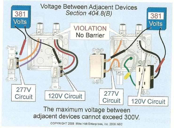
"Note my above post is not correct, the voltage between one phase of the 480/277 volt system and a different phase of the 208/120 volt system would be ~356 volts if there is a 120 degree difference. In most cases the 208/120 volt system would be supplied by a delta/wye transformer that would have its primary connected to the 480 volt supply. In this case there would be an additional 30 degree phase shift from the delta wye transformer and if this phase shift is positive, there will be a 150 degree difference between A phase of one system and B phase of the other system. This would result in ~385 volts between the ungrounded conductors. If the phase shift was negative, there would be ~301 volts. The resultant voltage is found by using the rule of cosines to add the voltage vectors.
c^2 =a^2 + b^2 -2abCOS(angle)
c^2= c squared
c is the resultant voltage
a is 120 volts
b is 277 volts
Don"
Then in post #19 you posted a graph from Smart. I understand the 277v and 120v lines being drawn the way they are (Being 120 degrees apart) but it's been awhile since school and I'm a little rusty with my math. Could you or anyone work Don's formula posted above to get at least one of the numbers presented in smarts graphic? Here's a link to the thread,
http://forums.mikeholt.com/showthread.php?t=86550&highlight=404.8(B)&page=2
Thanks, Mark