Typical Power Factor values for Commercial and Residential buildings.

Status
Not open for further replies.
Hi.


I'm designing a small complex of three stores. Everything is already set up, the only thing I need is an standard Power Factor value.


Is there some IEEE or ANSI standard with typical power factor values for commercial buildings?

By the other hand, I'm about to close a deal with a contractor for the designing a four-small-apartment building. Again, is there some IEEE or ANSI standard with typical power factor values for residential buldings?

I've already found some typical values. But you know, they're from the Internet, they got no legal value to support the designs.

Any suggestions?

What do you need power factor for? In general, you do not need to account for power factor for NEC calculations.
 

Smart $

Esteemed Member
Location
Ohio
Transformer sizing, for example.
Transformer sizing is in kilovolt-amperes (kVA)... so again, no need for power factor.

About the only time you truly need to know the power factor is if the power company charges for excessive power factor... and you need to size the power factor correction caps.
 
Transformer sizing is in kilovolt-amperes (kVA)... so again, no need for power factor.

About the only time you truly need to know the power factor is if the power company charges for excessive power factor... and you need to size the power factor correction caps.

I see.

Well, I was thinking about applying power factor for voltage drop calculation.

I normally use the NEC "Cmil VD Calculation", but there's another formula around that includes power factor. I'd like to learn how to use it for future designs.

I think that's the main reason why I need thoses values.

Any suggestion of where can I find them?
 
I see you are from Venezuela. Here in the US, we generally either use line current, or VA so we dont typically use power factor in calculations. Probably a PF of .85 would be adequate for many applications.

Oh, I see.

.85 is pretty close to some values I've found. But you know how legal stuff works. Values has to be from Technical Papes, Standards or Codes.

I'm trying to use power factor to calculate voltage drops. There's another formula besides those in the NEC that is "more precise". That formula includes the system's power factor. I'd like to learn how to use it for future designs.

Any last suggestion?
 

Tony S

Senior Member
Unfortunately typical values are all most of us have to go on. If you know the nature of the loads IE motors then you’re in with half a chance of a guessestimation and it is nothing more than a guess.

Ethan’s figure of .85 PF would probably be the base to work on.

I’m in an IEC country, normally the supply authority will tell the designer the maximum permitted PF variance allowed. It is then up to the designer to build in PF correction if required.
 

GoldDigger

Moderator
Staff member
Location
Placerville, CA, USA
Occupation
Retired PV System Designer
But I believe that VD does vary with PF. Say two cases of same voltage and same current but different PF, the VD will be different. I admit I dont really understand why.

The Southwire VD calculator http://www.southwire.com/support/voltage-drop-calculator.htm assumes .9 for PF.
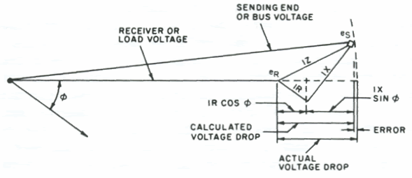
If you want VD to represent the difference in magnitude between the source voltage and the load terminal voltage then you have to do a vector calculation.
The voltage difference across the wire is resistive enough that it can be taken as in phase with the load current. That means the the voltage difference vector is not parallel to the original voltage vector.
That in turn means that the reduction in the magnitude of the load voltage is less than the magnitude of the voltage difference.
For a PF above about .9 it makes very little difference in VD.
The lower the PF the greater the effect.
A PF of zero would lead to VD being near zero also as long as the voltage difference was less than 10% of the input voltage.
I wish I had some nice pictures for the above. :)

Sent from my XT1585 using Tapatalk
 

Smart $

Esteemed Member
Location
Ohio
If you want VD to represent the difference in magnitude between the source voltage and the load terminal voltage then you have to do a vector calculation. ...
Well, that's one method. The other is essentially the algebraic form of it.

Approximate: Vd = IRcosθ + IXsinθ

IEEE Exact: Vd = es + IRcosθ + IX sinθ + sqrt(es^2 - (IXcosθ - IRsinθ)^2)
 

Smart $

Esteemed Member
Location
Ohio
Well, that's one method. The other is essentially the algebraic form of it.

Approximate: Vd = IRcosθ + IXsinθ

IEEE Exact: Vd = es + IRcosθ + IX sinθ + sqrt(es^2 - (IXcosθ - IRsinθ)^2)
Oops. I copied that formula from someone else post. I thought it looked kinda funny so I double checked. The red + should be a minus...

Vd = es + IRcosθ + IX sinθ - sqrt(es^2 - (IXcosθ - IRsinθ)^2)

...and it's easier to see how it compensates for the error in the approximate formula when written...

Vd = IRcosθ + IX sinθ + (es - sqrt(es^2 - (IXcosθ - IRsinθ)^2))

V-drop_diagram.gif
 
Last edited:

Besoeker

Senior Member
Location
UK
But I believe that VD does vary with PF. Say two cases of same voltage and same current but different PF, the VD will be different. I admit I dont really understand why.

The Southwire VD calculator http://www.southwire.com/support/voltage-drop-calculator.htm assumes .9 for PF.
Interesting that it asks for the current at the end of the run......

Anyway, the voltage drop calc needs to take account of both R and X for the chosen conductor.
Up to about 50mm^2 it is negligible. Even then it makes less than 0.02mV/A/metre. For copper. We don't often use Al.

By way of comparison. 50mm^2 is about 1/0 AWG.
 

Smart $

Esteemed Member
Location
Ohio
Interesting that it asks for the current at the end of the run......
That's just in case some gets away en route. :D

Anyway, the voltage drop calc needs to take account of both R and X for the chosen conductor.
Up to about 50mm^2 it is negligible. Even then it makes less than 0.02mV/A/metre. For copper. We don't often use Al.

By way of comparison. 50mm^2 is about 1/0 AWG.
Negligible tends to vary when looked at from a different perspective. Compare Vd at ampacity and .85pf and you get more realistic values.

GaugeVd(R)Vd(Z)
1440.546.5115%
1234.040.0118%
1033.036.0109%
834.5039.00113%
628.6031.85111%
424.6526.35107%
323.0025.00109%
221.8521.85100%
120.8019.5094%
1/019.5018.0092%
2/019.2517.5091%
3/017.60015.40088%
4/017.02014.26084%
25016.83013.26079%
30016.81512.54075%
35016.43011.78072%
40016.41511.05567%
50016.34010.26063%
Vd(R) & Vd(Z) values are for copper per 1000' in PVC conduit
 
Last edited:
If you want VD to represent the difference in magnitude between the source voltage and the load terminal voltage then you have to do a vector calculation.
The voltage difference across the wire is resistive enough that it can be taken as in phase with the load current. That means the the voltage difference vector is not parallel to the original voltage vector.
That in turn means that the reduction in the magnitude of the load voltage is less than the magnitude of the voltage difference.
For a PF above about .9 it makes very little difference in VD.
The lower the PF the greater the effect.
A PF of zero would lead to VD being near zero also as long as the voltage difference was less than 10% of the input voltage.
I wish I had some nice pictures for the above. :)

Sent from my XT1585 using Tapatalk

That's exactly origin of the formula I was talking about, Mr. GoldDigger. Thanks for answering.
 
Unfortunately typical values are all most of us have to go on. If you know the nature of the loads IE motors then you’re in with half a chance of a guessestimation and it is nothing more than a guess.

Ethan’s figure of .85 PF would probably be the base to work on.

I’m in an IEC country, normally the supply authority will tell the designer the maximum permitted PF variance allowed. It is then up to the designer to build in PF correction if required.

I see. Well, in that case I think I'm going to calculate my own values.

Thanks for aswering.
 
Status
Not open for further replies.
Top