verifying GFP is working

Status
Not open for further replies.

oldsparky52

Senior Member
A newly wired marina is about to come on line. There is GFP on the service disconnects and the pedestals.

I want to be sure the GFP actually works, using a real life fault. My idea is to take a 60-watt light bulb and connect it from hot to ground downstream from the GFP. The GFP should trip at no less than 100ma. I'm not trying to determine that threshold on this test, just that a 60-watt light bulb (should pull around 500ma) will trip the GFP.

The largest main is a 1200-amp breaker and it uses a CT and GFP monitor to trip the shunt trip on the 1200-amp breaker. I want to see that it actually works.

Am what I'm proposing seem dangerous or too mickey mouse to y'all? I see it as a true real world type of fault just to be sure the functionality of the GFP system works.

Comments?

Thanks.
 

Ingenieur

Senior Member
Location
Earth
We do something similar all the time
did it yesterday to a 700 HP vfd
shunted the dc bus and output (at 1, 5, 30, 60 Hz) to the X0
we use uses a resistor (ngr) and a momemtary pb/contactor
in this case the vfd operates at 0 Hz +/- 1/2 Hz most of the time
it holds torque on a conveyor belt tensioner

another method is to put a i source thru the ct
if a zero seq ct route one leg outside and plug something into a recept

I would use a 900-1000 Ohm R
fuse it at 1/5 A
wear gloves and ppe if not using a remote contactor
 
Last edited:

winnie

Senior Member
Location
Springfield, MA, USA
Occupation
Electric motor research
An intentional, controlled, current from hot to ground is IMHO a reasonable way to test the functionality of a ground fault system. On our (much smaller) lab GFP the 'off' switch actually runs a test current through a resistor to trip the GFP, so each time the system is turned off the GFP gets tested.

I would recommend using a suitably rated resistor rather than a lightbulb. The reason is that the resistance of a cold lightbulb is much lower then when it warms up and reaches steady state. This means that your 'test current' would be more like 5A, not 500mA.

I would also recommend using a properly installed circuit (breaker, suitably sized conductors, switch, resistor) rather than hacking together some test leads and a resistor; basically set things up so that you can test the GFP without having to 'work live'. If you make a mistake on a 1200A main, you probably have some serious fault current available and arc flash danger.

-Jon
 

steve66

Senior Member
Location
Illinois
Occupation
Engineer
An intentional, controlled, current from hot to ground is IMHO a reasonable way to test the functionality of a ground fault system. On our (much smaller) lab GFP the 'off' switch actually runs a test current through a resistor to trip the GFP, so each time the system is turned off the GFP gets tested.

I would recommend using a suitably rated resistor rather than a lightbulb. The reason is that the resistance of a cold lightbulb is much lower then when it warms up and reaches steady state. This means that your 'test current' would be more like 5A, not 500mA.

I would also recommend using a properly installed circuit (breaker, suitably sized conductors, switch, resistor) rather than hacking together some test leads and a resistor; basically set things up so that you can test the GFP without having to 'work live'. If you make a mistake on a 1200A main, you probably have some serious fault current available and arc flash danger.

-Jon

Very good points, especially about the light bulb drawing more current when its cold.

The problem with a resistor is that it will draw about 12 watts if the GFP doesn't trip. You could probably get by with something less than 12 watts if you only momentarily energize it, but it would be better to have it rated fro the full 12 watts.

Also good points about not working hot.

Of course they do make testers for this stuff, but I'm sure they aren't cheap.
 

Jraef

Moderator, OTD
Staff member
Location
San Francisco Bay Area, CA, USA
Occupation
Electrical Engineer
So you used the term "GFP monitor", and that makes me question this. There are Ground Current Monitors, and there are GF Protection (Trip) units, although sometimes the word "monitor" is also in their description. If you do have a GFP trip unit, chances are nearly 100% that it has a Test button or contact inputs, and as Winnie said, that's exactly how the test circuit works. Even the cheap ones that use a little toggle switch on the front are actually still doing the same thing and like he said, testing it every time you flip that switch.

But if what you have is only a ground current MONITOR, it likely does NOT have a trip function at all, so therefore "testing" it would be pointless unless you are interested in calibrating it.

If something in that device is wired to the shunt trip coil of the breaker, it's a trip unit and will already have a test function. You may have thought that the test function was only testing the relay contact operation, but on any GFP relay I've seen, it is actually testing the trip current value but shunting current to ground. I'd be surprised if you have a GFP trip unit without a test function and it would be interesting to hear what it is.

Years ago I had an Engineering Mgr who insisted that I build a trip test function into a system that used a GF trip unit set for 30A of ground current. He wanted me to literally wire a 30A contactor from line to ground and put a PB on the coil that said Test. I refused, I knew it could potentially explode! So I had to prove to him exactly how those trip units tested the GF current every time.
 
Last edited:

qcroanoke

Sometimes I don't know if I'm the boxer or the bag
Location
Roanoke, VA.
Occupation
Sorta retired........
What is the voltage of the 1200 amp breakers feed? if it is 150 volts to ground or more 230.95 (C) has something to say about testing.
Of course that article is for services.
 

Ingenieur

Senior Member
Location
Earth
Years ago I had an Engineering Mgr who insisted that I build a trip test function into a system that used a GF trip unit set for 30A of ground current. He wanted me to literally wire a 30A contactor from line to ground and put a PB on the coil that said Test. I refused, I knew it could potentially explode! So I had to prove to him exactly how those trip units tested the GF current every time.

that is std practice on mine power load centers
of course we have a 15 A ngr lol

we also use a variac looped thru the ct's
gradually raise until trip
the gf relays do have test buttons but unless that actually pushed i thru the ct and trips the cb not acceptable

we not only need to verify trip but also the level

each ckt has 3 gf protections
ct/relay on the branch
ct/relay on the ngr
pt/relay across the ngr

all tested weekly
 

oldsparky52

Senior Member
For some reason, when I try to reply to a post using the "reply with quote" button, My spacebar won't work.

The voltage is 120/240.

The fault current available per the PC is less than 15k.

The service disconnect has this (http://www.eaton.com/ecm/groups/public/@pub/@electrical/documents/content/il04915001e.pdf) monitor mounted in the enclosure monitoring a 500:1 CT (hots and neutrals feeding the dock panel are installed through this CT) and controlling the shunt on the Main service breaker.

I am curious, when that unit is set at 100ma, what is the actual fault current in the feeders? That 500:1 CT output would be 1 amp for every 500 amps on the conductors? If so, then a 100ma leakage in the service conductors would have an output from the CT of .02ma? Am I understanding this correctly?
 

Ingenieur

Senior Member
Location
Earth

scientific notation still messes me up at times :lol:

and if no gnd fault no net current from the ct
L1 + L2 + N fields = 0
current supply = current return

but a 15000 A gf = 30 A from ct
but you'll never see it, it will trip ~ 0.1 A
 
Last edited:

zog

Senior Member
Location
Charlotte, NC
Whoa..there are standards for this type of test and they sure do not use a light bulb. You need to determine pickup and timing of the GFP relay, that means it has to be a controlled test and is done by injecting current with a proper test set. Testing companies do this all the time since it is often a required test (Often witnessed by an inspector). I suggest you have someone come out and test this properly.
 

Ingenieur

Senior Member
Location
Earth
Whoa..there are standards for this type of test and they sure do not use a light bulb. You need to determine pickup and timing of the GFP relay, that means it has to be a controlled test and is done by injecting current with a proper test set. Testing companies do this all the time since it is often a required test (Often witnessed by an inspector). I suggest you have someone come out and test this properly.

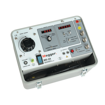
We use one of these for higher ranges
we have a lab quality i source for mA range
I don't believe testing is required in his case
he is it doing for personal edification and verification
it may not be feasible to pay a tesing outfit >$1000 to do so
ms2a.jpg
 
Status
Not open for further replies.
Top