voltage drop - again

Status
Not open for further replies.

muhandas

Senior Member
I apologize if this is not the correct forum for this question and would appreciate some guidance which forum would be more appropriate if this is not the right one.

This question relates to how to determine the voltage drop at non-dedicated receptacle outlets during an inspection at non-residential installations.

I know that NEC voltage drop requirements in the FPNs of 210.19(A)(1) and 215.2(A)(3) are not enforceable but there are some state building codes, such as in Florida, where the voltage drop requirements are included as part of the Energy Efficiency section of the Building Code and therefore are enforceable. For branch circuits the requirement states ?Branch Circuit conductors shall be sized for a maximum voltage drop of 3% at design load.?

The key term is ?design load.? Consider a branch circuit with 10 non-dedicated receptacles spaced arbitrarily. The design load would be 180 VA for each receptacle. Is there a way to determine the max voltage drop other than simultaneously loading every one of the ten receptacles with 180 VA and then measuring the voltage drop at the furthest one? This way strikes me as awfully clumsy.

Any suggestions from you folks in Florida or other states who need to deal with this would be greatly appreciated.

Thanks,
Heinz R.

Well we all have had plenty of time to review Chapter 13 of the 2004 Florida Building Code before the some what circus-like attempts at enforcement started. You my friend are the EE. You can call those 10 receptacles 200va or 2000va and do your voltage drop from there. Where in FBC Section 13-413.1.ABC.1 and 2 does it say you as the EE have to design as per NFPA 70 art 220? Common sense must prevail here.
 
Tx. for quick reply. But please look at this problem not as the EE but as what the Inspector would have to do to determine compliance with Chapter 13. If the Inspector decides to load the furthest receptacle with the maximum allowed (80% of the breaker rating) this would be far in excess of "the design load" of the Code, which is 180VA per receptacle for conductor sizing purposes.
I am the Inspector on this particular job and am really in a qaundary about how to proceed. What would be a practical approach?
Heinz R.
 
Wow, this sounds way more complicated than calculating a voltage drop.

It's simply resistance times current equals voltage (voltage is the voltage drop in this case).

The resistance of the conductors times the amperage through, or usually it's said "across" them.

1 amp across 1 ohm is 1 volt.

Some how I don't expect that even comes close to answering the question, it sounds like there are beaurocrats involved.
 
We each have a job in the install. Mine as the electrician is to install as per print specs. It falls onto the EE that made the specs. Your job is to see that i did my job and that i followed specs and nec. If end user has a voltage drop problem it's not your problem. Anything over 200 feet for an unknown load i would upsize the wire but NEC would not really care. Just how far are we talking about here ?
 
Actually, it is more complicated than it should be, but not in the technical sense of V=IR.

The discussion revolves around the definition of "design load" for general purpose branch circuit receptacles. As you can see in my original statement of the code requirement, the 3% maximum voltage drop applies to branch circuit conductors. Simple enough to measure and compute if you know the specific load(s). But for a branch circuit that has only general purpose receptacles the load is unknown.

One school of thought holds that the design load should be equal to the rated load, that is any receptacle, even the most distant one, should be loaded to the circuit rating (80% of the OCPD) to determine compliance with the 3% VD limit. Another school argues that for the purposes of computing branch circuit loads the NEC (in Section 220) indicates that receptacles are calculated at 180VA and, therefore, that's what the "design load" should be. But that interpetration leads to a potential underestimation of the load that could be on the farthest receptacle and therefore, would lead to underdesign and a than 3% voltage drop.

As an inspector, I'm trying to get a read on the what the writers of the original requirement had in mind.
Heinz R.
 
We each have a job in the install. Mine as the electrician is to install as per print specs. It falls onto the EE that made the specs. Your job is to see that i did my job and that i followed specs and nec. If end user has a voltage drop problem it's not your problem. Anything over 200 feet for an unknown load i would upsize the wire but NEC would not really care. Just how far are we talking about here ?
Jim:
It is part of my job to determine compliance with Chapter 13 of the FBC. That's the one that has the voltage drop requirement. If I load the farthest receptacle with 80% of the OCPD rating the voltage drop exceeds 3%. The contractor argues that this is not what "design load" means.
There's my problem
Heinz R.
 
I am not from Florida but I can understand your plight. My opinion would be that without an actual load in place you could not go above the load calculations found in 220 and not the 80% of the circuit. Troubles with using 80% besides it is not part of load calculations is you don't know where to apply the load since it is not for one appliance. 50% would be what you would need to use if you where to consider one load at the end of the circuit. But I still would not use the percentages.
 
I'm going to have to think about this one. My first reaction is that the NEC is not a design manual, and the value of 180 VA is not a design load. It is used as the basis for sizing the service and sometimes feeders. But I will contend (and others on this forum have disagreed) that it is not required to be used as thebasis for designing branch circuits.

My second reaction is that the phrase you quoted from the building code speaks about a design activity. It is not written in "test after construction" kind of language. An inspector is not a party to the design process. How would an Inspector verify that my design properly accounted for that 3% VD?
 
Charlie:
Thanks for your thoughtful reply; you obviously see my problem. As a plan reviewer/inspector I do need to determine compliance with that requirement. It is part of Chapter 13, the Energy Efficiency chapter, of the Florida Building Code. The quotation of the requirement that I had in my original posting is all there is with regard to branch circuit voltage drop. Now, when there are defined loads, or receptacles with intended uses, it is no problem to determine compliance either with the plans or in the field.

The problem occurs with branch circuits that either include general purpose receptacles, or may be composed only of general purpose receptacles. How is the 3% VD to be determined in those cases? The requirement mentions "design load." I understand that the 180VA of NEC Section 220 is intended only to size conductors and panels but it is the only guidance I could find in the Code.

Thanks for your help.
Heinz R.
 
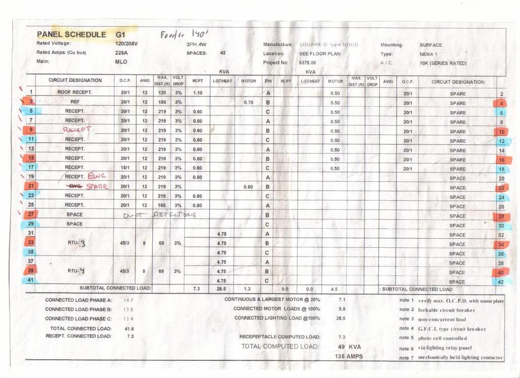
Here is a PNL sched that handled rec loads from a job I just did.

PNLschedG1.jpg


Lets look at G1 13 for instance. This circuit has 6 general office recs on it. 12 wire at 219'. Lets load the last rec at 16A.

2?219?1.93?16=13525

13525?1000=13V

13?120=11% VD

So I would guess thats not how this EE figured it.
 
...

One school of thought holds that the design load should be equal to the rated load, that is any receptacle, even the most distant one, should be loaded to the circuit rating (80% of the OCPD) to determine compliance with the 3% VD limit.
FWIW, general purpose receptacle circuits are considered non-continuous loads and therefore can be loaded to 100%.

As for the 3% VD requirement, my instincts tell me to base it on a 100% load at the farthest receptacle. Whether that is the intent of the requirement, I surely don't know :confused:
 
Here is a PNL sched that handled rec loads from a job I just did.

PNLschedG1.jpg


Lets look at G1 13 for instance. This circuit has 6 general office recs on it. 12 wire at 219'. Lets load the last rec at 16A.

2?219?1.93?16=13525

13525?1000=13V

13?120=11% VD

So I would guess thats not how this EE figured it.

This EE based the 3% on the 600va for the circuit.

2?219?1.93?5=4226.7

4226.7?1000=4.2

4.2?120=.035 or close to 3%VD.

So how do you inspect that?:-?:D

I feel you pain, this FBC Chapter 13 thing has been a thorn in my side for some time also. Good luck.
 
As a plan reviewer i see this differant than as inspector. I have no idea how you could know how the wire will be ran from that print. This could be a pole in middle of a warehouse and the run might only be 100 feet if in pvc in a slab or 200 feet if this is up to truss and back down and squared off for looks. It is totally unfair to hand you the job of determining the load and voltage drop. It might be 300 feet but only intended to run a computer and lamp at a loading dock. Even with misuse of a huge fan everything would be ok. Then again it might get a plug in air compresor. You could spends countless hours and still be wrong. Down side is if i am bidding this job and it does not spec #10 for that 20 amp receptacle then your getting #12. Ever think some houses out.? That 14-2 might be 100 feet to the first box and then back staps thru 10 devices before it gets to last outlet some 80 feet later. Now plug in that monster vac and bet your way over 3 % but will still work fine. What was voltage at the pole ? 125 ? 115 ? Could make a problem. And as the field inspector i hardly think you have the time to check. I have been given jobs that are over 600 feet from main disconnect to my first panel. Often i dought i will not end up with a problem but i am told to build as per print. Just who do we go after if there is a problem ?
 
This EE based the 3% on the 600va for the circuit.

Chris:
You're right and this raises the question why did the EE assume a 600VA load for the 6 receptacles unless he knew exactly what was going to be connected to them? And I doubt that because 600VA is also assumed for all the other receptacle circuits.

By the way, 600VA for six receps is 100VA per receptacle and that is even less than the 180VA per receptacle indicated in 220.14 of the NEC as the load value to be used for receptacles for sizing conductors and panels (with certain exceptions.)

Heinz R.
 
As for the 3% VD requirement, my instincts tell me to base it on a 100% load at the farthest receptacle. Whether that is the intent of the requirement, I surely don't know

Smart$ -
That certainly would be the most conservative approach, one that guarantees that a VD of 3% could never be exceeded regardless of how the circuit is loaded. But this "worst case" condition happens very rarely and all other circuit that would be loaded far more lightly would be penalized with having to use bigger gauge conductors or more sub-panels with all the associated increases in cost.

As a point of interest, an AWG 12 conductor carrying 16A in a 120V circuit reaches a 3% VD at 56 ft., that's not very long or even realistic or practical. (At 20A the 3% VD is reached at 45 ft.) This means that a 60 ft run with possibly a table lamp or a computer at the end receptacle would need to be wired with AWG #10 just because it would be tested at the 16A (or 20A) worst case condition. I would expect that most 20A circuits will have to be wired with #10 or even #8 if the receptacle outlets are some distance from the panel. And that's without knowing what will be connected at this recepatcles.

Could you imagine a 250 ft. run (something along the lines of Charlie's panel) at the end of which is a string of 6 receptacles? In this case an AWG #6 still has a 3.3% VD at 16A load current. To me that's just overkill.

There needs to be some common sense in the requirements - or perhaps general purpose receptacles (those without a "design load") ought to be exempt from having to meet this particular requirement.

Heinz R.
 
?Branch Circuit conductors shall be sized for a maximum voltage drop of 3% at design load.?

Untill further notice, FBC 13-413.1.ABC.1.2 is one sentence.

I am the Inspector on this particular job

Please excuse my first post/rant. When I clicked on your profile it says Engineer, so I figured you where designing this.

There needs to be some common sense in the requirements - or perhaps general purpose receptacles (those without a "design load") ought to be exempt from having to meet this particular requirement.

Heinz R.

Agreed. What is really refreshing here is an inspector looking into what chapter 13 really means. I have been struggling with this for a while now. I have redesigned lighting loads as per 13-415.1.ABC.1.1 and the article in question, yet I am to have one inspector look to see if the system was even programed???

Good luck Heinz, keep us posted.
 
...There needs to be some common sense in the requirements...

Leniency is seldom written into regulations :grin:

I do (with emphasis) understand your plight... but you are talking with a person that can help you decide how to implement this regulation no more than a fly on the wall could ;)

Have you made any attempt to get anything in this regard from the building commission or whatever branch of government it is down there that had the brainstorm :rolleyes: to begin with?
 
Please excuse my first post/rant. When I clicked on your profile it says Engineer, so I figured you where designing this.

Chris:
I indeed am a Florida P.E. I also work for a private provider of building code code services (of course, not on any projects to which I may have contributed in a design role,) and on this project I was/am the inspector.

But even as the EE, as you appreciate, the proper understanding and application of that VD requirement is important because you need to know how the AHJ will interpret it so you can design for it.

Essentially, what's needed is a definition of "design load" for general purpose receptacles, something that inherently has no design load.

As I had pointed out above, the worst case assumption for general receptacles is rather impractical in the real world and some sort of a compromise is needed that embodies the spirit of the requirement, say a maximum VD of 3% at 150 ft, which could easily be tested for during site inspections. This requirement makes the reasonable (IMHO) assumption that although some circuits would exceed 3% VD at the farthest receptacle, many other general purpose receptacle circuits would be loaded quite lightly, well below the 3% VD level, so that on average, considering many such circuits, the 3% requirement would be met.
This would certainly serve the Energy Efficiency intent of the Code.

Heinz R.
 
Smart$

You're right that leniency is not written into requirements but exceptions or special situations often are, and I believe that one such special situation exists here.

I have submitted a request for informal interpretation of that requirement as applied to general purpose receptacles and it will take some weeks to get a response. The problem with these requests for interpretation is that they have to be worded in a fashion that can be answered with "yes" or "no."

My submittal is worded in such a way that it asks whether it is the intent of the requirement that compliance to it could be determined with a VD drop measurement at the farthest receptacle at 80% of rated circuit current. If the answer is "yes" then the intent was indeed to apply the worst case situation and we will face a real cost problem in the real world. If the answer in "no" then we face a different problem since there will be no explanation of how determination of compliance could be made. The only thing we will know is that the worst case scenario is not to be applied. In all other respects we're back to square 1.

We will also in all likelihood be submitting a request for code modification but since the code cycle is not open at this time this request, even if it is agreed to, would take years to become effective.

In any event, I'll keep this group informed as I learn more.

In the meantime, all ideas, suggestions, and opinions are appreciated.

Heinz R.
 
Status
Not open for further replies.
Top