http://forums.mikeholt.com/showthread.php?t=195493&page=2
That is a different calculation based on the same basic physics.
The equation 2 K I D / VD = CM breaks down to:
2 -- multiplying factor since you are going out and back. (You might use other factors for 3 phase calculations or well balanced line-neutral situations)
K -- this is the resistivity of copper, given in ohms per circular mil per foot. You could have a different K for aluminium, different temperatures, or if you use different units (square mm and meters for example)
I -- this is the current required by the load
D -- this is the distance, given in the same units you used for distance in K
VD -- this is the allowed voltage drop in volts
CM -- the cross section in circular mils
If you know the circular mill area of your wire and want to know the voltage drop, you just flip the equation around:
2 KID / CM = VD
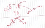
So you would generate the same sort of table that Gary gave, showing the total current flowing on each section of the 'map' of the circuit. Then using the wire size for each section of the map use the above equation to calculate the voltage drop for that section. At each load, the voltage drop is the total of all the section drops from the source.
This is only an approximation, since the current consumed by a load will change with the voltage applied to it, and the K factor changes with things like temperature. But for only a few % voltage drop the approximation is usually close enough.
-Jon