why does uneven voltages indicate a neutral issue?

Status
Not open for further replies.

jselesk2

Member
Location
Cleveland, Ohio
Suppose we have a single-phase, 3-wire residential electrical system with Leg #1 to neutral at 110v and leg #2 to neutral at 130v.

After reading a few threads on this issue, it seems that the general consensus is that this type of problem is most likely caused by a "neutral issue". I have two questions regarding this -

1) What type of "neutral issue" exactly are we talking about? Loose connection somewhere?

2) How exactly does this issue cause the voltage imbalance between the legs?

Thank you.
 

Besoeker

Senior Member
Location
UK
Suppose we have a single-phase, 3-wire residential electrical system with Leg #1 to neutral at 110v and leg #2 to neutral at 130v.

After reading a few threads on this issue, it seems that the general consensus is that this type of problem is most likely caused by a "neutral issue". I have two questions regarding this -

1) What type of "neutral issue" exactly are we talking about? Loose connection somewhere?

2) How exactly does this issue cause the voltage imbalance between the legs?

Thank you.
The neutral fixes each of the two legs at 120V wrt neutral. With no neutral, you get 240V across the two loads. The voltage across each will depend on its impedance. It's a 240V circuit series circuit and Ohms Law applies and voltages will divide according to the impedance of each "half". If, as is probable, those impedances are not equal, the voltages will not be equal.
 

jselesk2

Member
Location
Cleveland, Ohio
The neutral fixes each of the two legs at 120V wrt neutral. With no neutral, you get 240V across the two loads. The voltage across each will depend on its impedance. It's a 240V circuit series circuit and Ohms Law applies and voltages will divide according to the impedance of each "half". If, as is probable, those impedances are not equal, the voltages will not be equal.

So are you telling me that all 120v circuits in a home are actually 240v series circuits with the neutral acting as a resistor that drops the voltage to 120?
 

kwired

Electron manager
Location
NE Nebraska
So are you telling me that all 120v circuits in a home are actually 240v series circuits with the neutral acting as a resistor that drops the voltage to 120?
No they are all connected across 120 volt sections of the supply, but should the neutral path back to the source fail- whatever is connected to L1 becomes in series with whatever is connected to L2 - and there is 240 volts between L1 and L2.


ADD image:
 
Last edited:

jselesk2

Member
Location
Cleveland, Ohio
No they are all connected across 120 volt sections of the supply, but should the neutral path back to the source fail- whatever is connected to L1 becomes in series with whatever is connected to L2 - and there is 240 volts between L1 and L2.


ADD image:

That makes perfect sense for MWBCs, but say for example I opened up my home service panel and I did a voltage test directly off the bus bar to the main neutral wire. What would explain a voltage difference between the two legs and the netural in this case? Is the two hot feeder wires and the main neutral considered a MWBC and can the same logic apply there?
 

ggunn

PE (Electrical), NABCEP certified
Location
Austin, TX, USA
Occupation
Consulting Electrical Engineer - Photovoltaic Systems
That makes perfect sense for MWBCs, but say for example I opened up my home service panel and I did a voltage test directly off the bus bar to the main neutral wire. What would explain a voltage difference between the two legs and the netural in this case? Is the two hot feeder wires and the main neutral considered a MWBC and can the same logic apply there?

If the neutral is disconnected from the panel the line to neutral conductor voltages will totally depend on the impedances of the 120V connected (and turned on) loads. They will sum to 240V. Unless the neutral in the panel is disconnected from the neutral at the service transformer, the line to neutral voltages measured at the panel busbars will both be 120V.
 

junkhound

Senior Member
Location
Renton, WA
Occupation
EE, power electronics specialty
That makes perfect sense for MWBCs, but say for example I opened up my home service panel and I did a voltage test directly off the bus bar to the main neutral wire. What would explain a voltage difference between the two legs and the netural in this case? Is the two hot feeder wires and the main neutral considered a MWBC and can the same logic apply there?

Another variation:

Some transformers have secondary taps to change voltages by a few percent to account for primary line losses.
Different number of transformer winding turns (e.g wrong taps) on each leg will give different voltages.
 

gar

Senior Member
Location
Ann Arbor, Michigan
Occupation
EE
180605-1140 EDT

jselesk2:

You need to find a junior college with some good electrical circuit theory classes and take them, or at least find some books on the subject and study them.

.
 

Craigv

Senior Member
180605-1140 EDT

jselesk2:

You need to find a junior college with some good electrical circuit theory classes and take them, or at least find some books on the subject and study them.

.

It's fairly easy to build a low voltage test rig with a 12v center-tap transformer and several light bulbs. Adding and subtracting loads to each phase leg will show how voltage varies on each leg but always equals the total transformer voltage.
 

JFletcher

Senior Member
Location
Williamsburg, VA
You can quite easily simulate the effect of a lost service neutral by performing the following experiment:

Wire up a multiwire branch circuit, put one receptacle on each leg. Put a switch on each conductor... Three switches and total, one on each hot Leg, one on the neutral. Get two cheap shop lights with clamps. Buy an assortment of light bulbs from 20 watt to 100 watt.

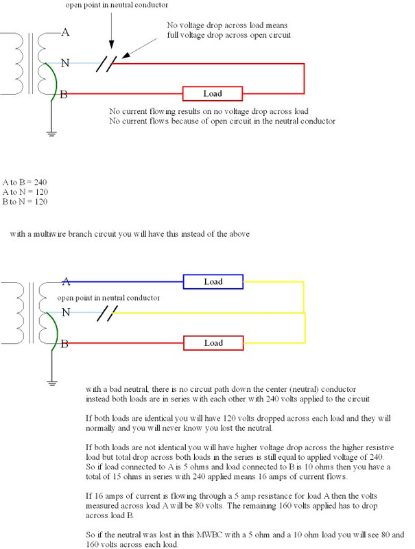
First test... Connect a shop light to each receptacle, install 60 watt bulbs in each. Switch on your neutral, then switch both Hots on. The bulbs will be glowing at nearly the same intensity. Now, turn the switch for the neutral off to simulate a break in the neutral. The lights, having the same impedance, should not change intensity except for maybe a very minor bit due to manufacturing differences. With the neutral open, they are now operating in series at 240 volts rather than at 120 volts in parallel. The voltage has doubled, however the resistance has also doubled, so amperage draw remains the same. Both lights or loads have the same impedance, so they still see the same voltage across them as with the neutral closed.

Test number 2, replace one of the bulbs with a 40 watt bulb, and repeat test number one. You will notice when you open the neutral that the 40 watt bulb will glow brighter as it has a larger voltage across it now than the 60 watt bulb. Having 60% of the circuits resistance, it will see 60% of the voltage. Operating at 144 volts will seriously reduce its lifespan, while the 60 watt light bulb is only seeing 96 volts.

Third, repeat the test again this time with a hundred watt bulb and a 20 watt bulb. When you switch open the neutral this time, the 20 watt bulb will glow very brightly than burnout as it is seeing 200 volts (5x + x=240v, x=40). As soon as it burns out, the hundred watt bulb will go out as there is no longer a complete circuit. Now close the neutral switch, it will work normally seeing 120 volts.

When there is no neutral present, the loads operate in series at 240 volts and voltage across something is determined by its impedance. As you can see, the lower wattage items are the ones that see the over-voltage when you lose neutral, that's why you typically blow up electronics and other high resistance/ lower wattage appliances instead of things like coffee pots, space heaters, and microwaves, though it is quite possible for those to get damaged as well.

Visually, one of the first signs of a failing neutral is watching some light bulbs get brighter, while others get dimmer. Conducting the above tests in a safe and controlled manner lets you see the results of a failed (open) neutral, allows you to measure voltages, and most importantly understand the phenomenon and be able to recognize that almost immediately when it happens on a customer's property.
 

Strathead

Senior Member
Location
Ocala, Florida, USA
Occupation
Electrician/Estimator/Project Manager/Superintendent
Suppose we have a single-phase, 3-wire residential electrical system with Leg #1 to neutral at 110v and leg #2 to neutral at 130v.

After reading a few threads on this issue, it seems that the general consensus is that this type of problem is most likely caused by a "neutral issue". I have two questions regarding this -

1) What type of "neutral issue" exactly are we talking about? Loose connection somewhere?

2) How exactly does this issue cause the voltage imbalance between the legs?

Thank you.

EDIT Oops forgot to attache the files.

View attachment circuit diagram no math.pdf View attachment circuit diagram.pdf

Try this. I use it for my second year apprenticeship class. I suggest you try to work through the "no math version" and only use the other one to check your results. I already gave you many of the formulas required. If they don't make sense then by all means get in to a class that will instruct you, please.

Note that regarding your question about reading it at the main panel. If you have a loose neutral you will read the imbalance everywhere beyond that point electrically until you get to a point where you are reading the neutral "clean" because the neutral is a resistance.
 

GoldDigger

Moderator
Staff member
Location
Placerville, CA, USA
Occupation
Retired PV System Designer
Note that even more than a static unbalance condition at the service entrance (which could be the result of heavy unbalanced loading on the POCO secondary from other sources, or a tap mismatch (less likely to happen when POCO uses a single pot to produce 120/240), the definitive sign of a compromised neutral is that one leg's voltage to "neutral" increases as you add load to the other leg.
 

kwired

Electron manager
Location
NE Nebraska
That makes perfect sense for MWBCs, but say for example I opened up my home service panel and I did a voltage test directly off the bus bar to the main neutral wire. What would explain a voltage difference between the two legs and the netural in this case? Is the two hot feeder wires and the main neutral considered a MWBC and can the same logic apply there?
Not a "branch circuit" but the supply circuit is still "multi-wire", you just have all the loads on L1 in series with all the loads on L2 if you lose the neutral on the supply circuit.

Another variation:

Some transformers have secondary taps to change voltages by a few percent to account for primary line losses.
Different number of transformer winding turns (e.g wrong taps) on each leg will give different voltages.
Not saying you can't run into this, but aren't such taps typically on the primary side of the transformer?
 

JFletcher

Senior Member
Location
Williamsburg, VA
New Transformers I have seen, if they are fed the way they are intended, the Taps will be on the primary side. A 480-volt to 120 / 208 volt transformer usually has 7 taps... A 0 tap, plus and minus 2.5%, plus and minus 5%, and plus or minus 7.5 or 10%, allowing anywhere from 432 volts up to 528 volts on the primary to give a correct/desired secondary voltage. I have seen more than one of these wired on the minus 5% tap even with 480 volts from the Poco to allow 230/460 volt motors to run closer to 230 (well, 218 or so)volts than 208 volts, while keeping line to neutral loads around 125 volts ( high but tolerable).
 
Status
Not open for further replies.
Top