In the “old days,” at least two forms of CT compensation for a transformer differential scheme were usually necessary.
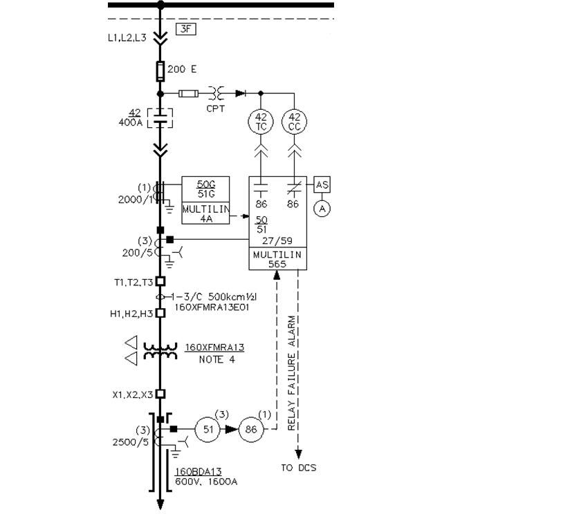
Often, the transformer was delta-wye (star). This creates a phase shift between the primary and secondary. The differential CTs needed to compensate for the phase shift with the CT connections. In the US, this was done using wye connected CTs on the transformers delta side and delta connected CTs on the wye side. Since the OP is delta-delta, this wasn’t an issue assuming proper polarities are observed.
To speak to my cited statement, the other necessary compensation is to make the CT secondary currents as close as possible in magnitude. Ideally, assuming a common CT secondary rating, the ratio of the CT primaries would be the inverse of the transformer’s associated voltage ratio. In the case of the OP the voltage ratio is 4160/480 or about 8.7. Ideally then, the ratio of the CT primaries would be about 0.115. The 4160V side uses 200A, so the 480V side would need to be 200A/.115 or about 1733A. While such a CT could be manufactured, it isn’t usually practical. Using a 2000/5A CT would introduce about a 15% magnitude error. Judicious selection of other CTs might get closer. Most “old days” mechanical type transformer differential relays had the ability to be desensitized to that level of error but couldn't handle the 44% error a 2500/5A CT would introduce.
One other consideration; while it was never a requirement in the US, IEC standards require that one side of a CT secondary be grounded. That creates havoc with wye connected transformer windings since all the CTs must be wye connected. Another set of compensating 1:1 (or 5:5) CTs were needed to negate phase shift problems.
Modern electronic relays commonly use all wye connected CTs and compensate for both phase shift and CT primary mismatch in the relay's algorithms.