fbhwt
Electrical Systems Inspector
- Location
- Spotsylvania,Virginia
- Occupation
- Electrical Systems Inspector
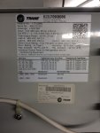
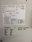
Trying to figure out the proper wire size and over current protection for this VFD on this air handler, the electrical contractor wired this with 3-#6awg and #12 ground by way of 50a breaker. The drawings for this building show this air handler (AHU-1) with 1 20hp motor but, there are 2 20hp motors. I am being told by an engineer that I need 3 #4awg and #6g, OCP at panel to be 110a. The picture is from the drive cabinet.