• We will be performing upgrades on the forums and server over the weekend. The forums may be unavailable multiple times for up to an hour each. Thank you for your patience and understanding as we work to make the forums even better.

wiring an 11 pin relay for a start stop switch for a hot tub?

Merry Christmas
Status
Not open for further replies.
Location
Missouri
Occupation
Electrician
I have a hotel with a two push botton start/stop setup for the hot tub jets, with a 19v timer relay in a mechanical room.

The old relay apparently blew out and the maintenance tech basically disassembled it all without taking any pictures so I don't know how it was set up before. I don't normally deal with this. They called me up randomly asking if I could fix it because they can't get anyone else out.

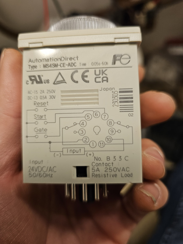
My understanding is that it should be wired something like this?


There are 2 16/2 wires coming from the start/stop switch, and there appear to be two 19v line/neutral feeds in this junction box where the relay was unceremoniously stuffed inside. Unlike the picture linked here, there are no light outputs. It's just the start stop switches and the two 19v feeds coming into the relay.

How should this be wired?
 

Krusscher

Senior Member
Location
Washington State
Occupation
Electrician
Hook it up like the picture but run your power for your contactor coil for the jets through 11 and 9. ignore the red wires and and the wires going to the lights unless your jet contactor coil actually uses 19v which is a strange voltage to have to be honest.
 

Krusscher

Senior Member
Location
Washington State
Occupation
Electrician
Save for the fact that it is listed for 15vac.
What is your power supply rated output?
With that relay I believe you would use Time Off Delay. 11 will be your Jet Contactor coil power in (constant voltage of what ever your coil is rated for) 9 will be Jet Contactor coil out. 19v power will go to both of your buttons which should both be normally open contacts. Start will feed back to 6 and stop will feed to 7. 19v hot and neutral will go to 2 and 10.
 
Location
Missouri
Occupation
Electrician
I was wrong. It's 120v coming in and 12v for the relay.

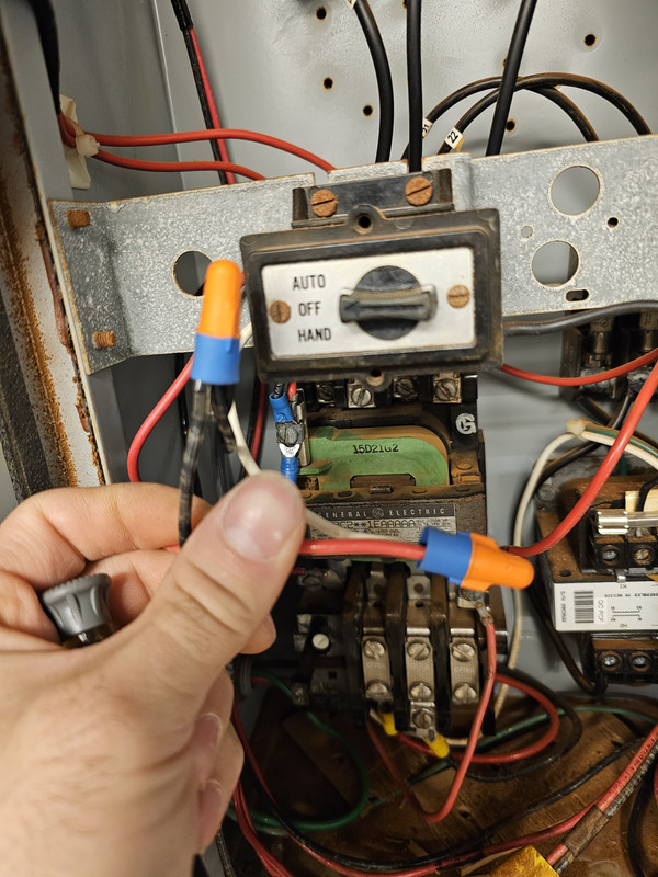
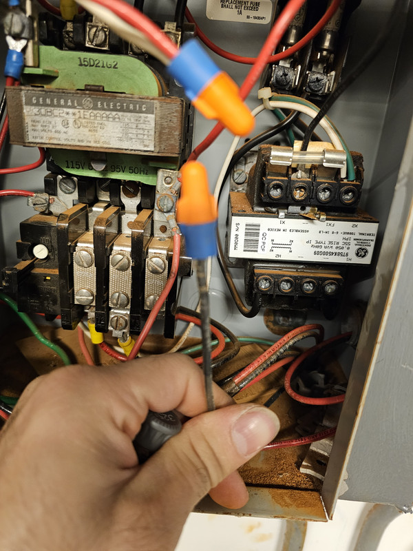
This is the 120v feed in the main shutoff

This is the 12v contacter feed

This is the associated return wire for the 12v feed that was just capped off in the shut off

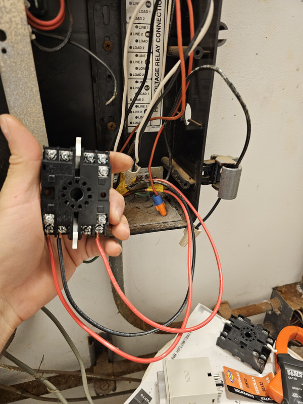
The relay. Black wire capped off in the back is the same as the black wire capped off in the shutoff

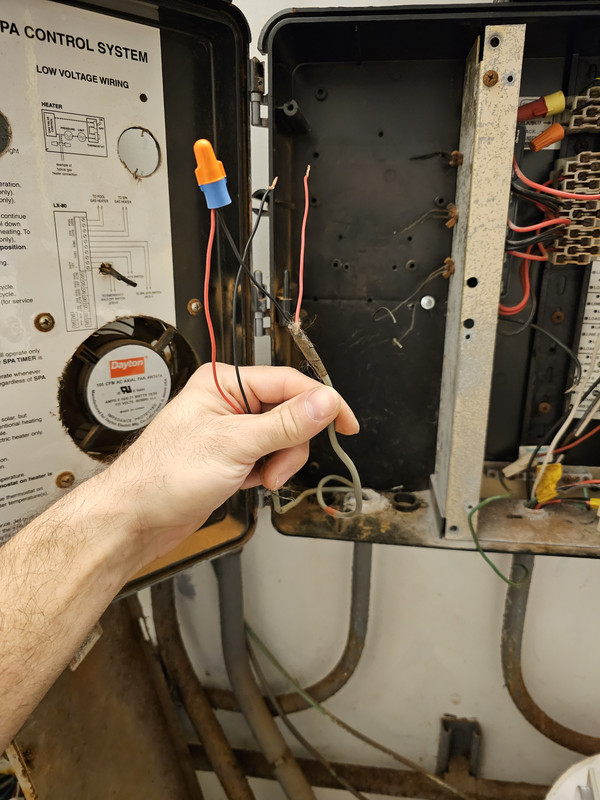
Wires going to the separate start and stop switches. I have the red feeding into stop switch which comes back and splices to the red of the start switch and then comes back to this junction box.

The actual relay
 

Krusscher

Senior Member
Location
Washington State
Occupation
Electrician
It's hard to tell you how to do this without being there. might help to label each wire and land them on the relay the way I said to then take a clear picture of the relay base and we could see if you got it right from there. I am sure you can figure this out by looking at it as well. Just hook it up in a way that makes sense, there is not much you can do wrong as long as you don't hook up the wrong voltage to the power supply on the relay so just make sure your 120v for your contactor is on on one of the 2 dry contacts and the worst that will happen is the pump will come on at the wrong time.
 
Status
Not open for further replies.
Top