Whale Rage Forever
Member
- Location
- Missouri
- Occupation
- Electrician
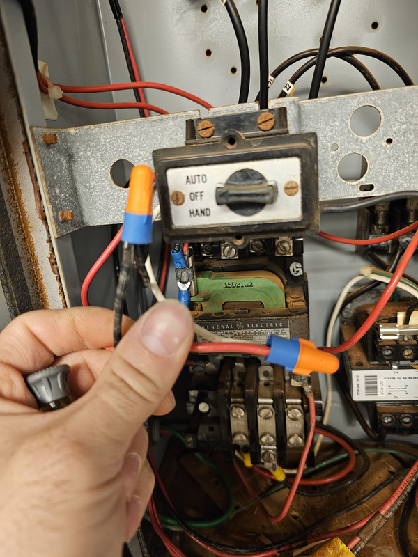
I have a hotel with a two push botton start/stop setup for the hot tub jets, with a 19v timer relay in a mechanical room.
The old relay apparently blew out and the maintenance tech basically disassembled it all without taking any pictures so I don't know how it was set up before. I don't normally deal with this. They called me up randomly asking if I could fix it because they can't get anyone else out.
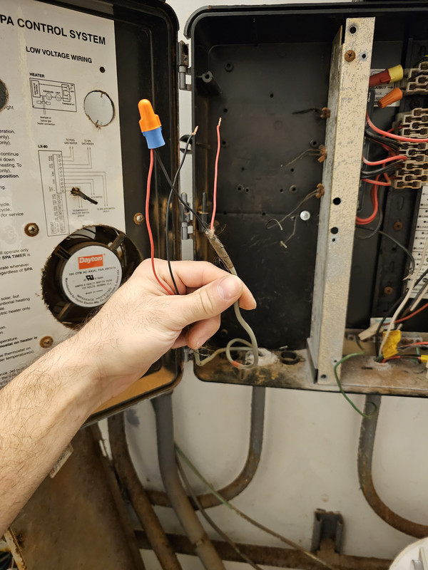
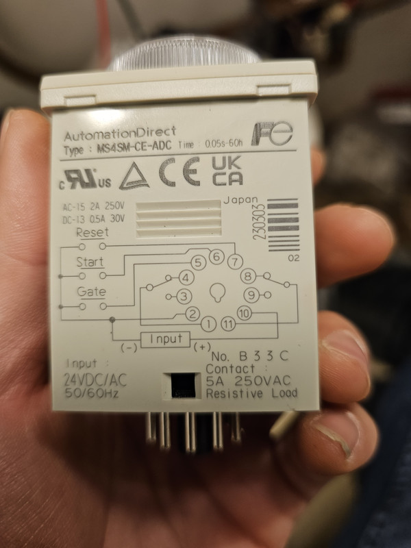
My understanding is that it should be wired something like this?
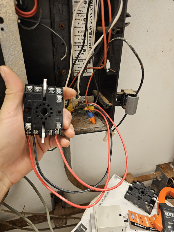
There are 2 16/2 wires coming from the start/stop switch, and there appear to be two 19v line/neutral feeds in this junction box where the relay was unceremoniously stuffed inside. Unlike the picture linked here, there are no light outputs. It's just the start stop switches and the two 19v feeds coming into the relay.
How should this be wired?
The old relay apparently blew out and the maintenance tech basically disassembled it all without taking any pictures so I don't know how it was set up before. I don't normally deal with this. They called me up randomly asking if I could fix it because they can't get anyone else out.
My understanding is that it should be wired something like this?
There are 2 16/2 wires coming from the start/stop switch, and there appear to be two 19v line/neutral feeds in this junction box where the relay was unceremoniously stuffed inside. Unlike the picture linked here, there are no light outputs. It's just the start stop switches and the two 19v feeds coming into the relay.
How should this be wired?