Wye - Delta Bank

Status
Not open for further replies.

Basra123

Member
I still didn't get an exact answer to this question: here is it again.
you have 3 single phase transformers arranged in an ungrounded wye primary and centertapped delta secondary. Assume the center-tapped transformer with leads L1, N, L2 is in the middle and the other two transformers on either side with their wild leg P tied tied together.
Now, when the primary winding on the transformer on the left side or right side of the centered tapped is shorted but not to ground what will be the voltages between :

L1 & L2 =
L1 & N =
L2 & N =
P & N =
 
Re: Wye - Delta Bank

If not to ground, where is it shorted? Another phase or the ungrounded neutral?
 
Re: Wye - Delta Bank

The wild legs are shorted to what if not to ground? This seems like a valid question to me?
 
Re: Wye - Delta Bank

Basra,

This is trickier than I thought. I see that the primary voltages on the good transformers will increase by a factor of 1.732, and the angle between them will change from 120 to 60 degrees.

You must assume that the secondary of the shorted transformer opens so that it does not short the delta.

Will work out a better answer for you. Hurricanes on my mind today.
 
Re: Wye - Delta Bank

Rattus,

Why the angle changes from 120 to 60 when the third phase still connected. when one primary is shorted to the star point, we still have 3phase system, i.e., 2 lines connected to the top of the good two windings and the third line to the star point thus a three phase system still exists and angle should be 120. What are your thoughts?
 
Re: Wye - Delta Bank

I would need the problem stated a little simpler to understand. If I could understand the problem, I might take a crack at the math.
 
Re: Wye - Delta Bank

Basra,

Let's reword your problem. To get around the shorted transformer problem, let's say the transformer A secondary is open. Also let voltages Va, Vb, & Vc be the phase voltages relative to the 4th wire which is at ground potential.

Now draw the vector diagram for the wye. Then the floating neutral does just that. Its voltage and phase float around with load changes.

Now short the primary of transformer A to N, and the wye becomes a vee, and the phase separation changes to 60 degrees, and the primary and secondary voltages are increased by a factor of 1.732.

This gets rather sticky, but the secondary voltage from transformer A is now increased by a factor of 3! I can see I am going to have to provide vector diagrams.

Anyone else care to offer an opinion?
 
Re: Wye - Delta Bank

Basra,

Here is another way to look at this problem:

Consider a 3-wire, 3-phase service and a wye/delta transformer.

Now connect two of the phase wires correctly and connect the third to the neutral. This leaves one primary open, so just remove that transformer because it does nothing. This leaves us with an open delta.

Now let the secondary voltages be:

V21 (center tapped at N) Your L2-L1
Vp2 Your P-L2
V1p (open leg) Your L1-P

Please note that V12 and V21 for example are 180 degrees apart in phase.

Assigning arbitrary phase angles, the normal voltages are

V21 = 240V @ 0
Vp2 = 240V @ 120
V1p = 240V @ 240

BUT, the primary voltages are 1.732 higher than normal, and the polarity of one of the transformers is reversed, then:

V21 = 416V @ 0
Vp2 = 416V @ -60
V1p = 720V @ 150

If you don't know trig, just draw these vectors out to scale and measure the length of V1p.
 
Re: Wye - Delta Bank

Still more:

Vpn = 550V @ -41

Now how about some of you engineers out there double checking me on this. I squirted WD40 on my brain, but it is still rusty. Need some reassurance.
 
Re: Wye - Delta Bank

rattus,

There is lots of information and things are cloudier now...however, I can see the 1.732 factor due to the line voltages being applied on the primary of the two good transformers. Please remember there is not neutral wire here....and when one primary is shorted to the star point that means we still have 3 lines connected to the 2 phases. The questions is why the angle changes to 60? if u draw the vector diagram for the three phases and then remove one phase you still have 120 between the other 2 phases. I mean waht cause the angle to become 60 between the remaining 2 phases?
Also, if the primary voltage is shorted on then that will be reflected on the secondary and means the the other 2 phases are now in parallel thus the leads L1 is connected to P and voltage between them is zero and not 720. the other voltages between L1 & L2 = 416, L2 & P = 416, and P & N = 550. The latter is based on 416 <0 +208<120 degrees
 
Re: Wye - Delta Bank

Basra,

You must compute the voltage and phase across each primary.

Draw the wye diagram such that the vectors are,

V1 = Vp @ 90
V2 = Vp @ 210
V3 = Vp @ 330

where Vp is the magnitude of the primary voltages.

These voltages and angles are fixed by the poco and cannot change. They exist whatever we do.

Now short N to V1,

V21 = V2 @ 210 - V1 @ 90 = 1.732Vp @ 240
V31 = V3 @ 330 - V1 @ 90 = 1.732Vp @ 300

This happens because the vectors are connected tail to tail (wye) instead of head to tail (delta).

This means that the primary is wired for a wye, but the secondary is wired for a delta. The result is that instead of the secondary vectors forming an equilateral triangle with sides equal to 416V, an isosceles triangle is formed with sides of 416, 416, and 720V.

This is not unlike an earlier problem where the transformer polarities caused voltages to cancel. However, in this case, the vector sum is increased rather than decreased.

Let's get this point straight before we proceed.

[ September 24, 2005, 11:58 PM: Message edited by: rattus ]
 
Re: Wye - Delta Bank

Rattus,

Ok, performing the vector addition make sense and I follow you now....but I want to make sure that going back to my labeling of L1,N,L2 for the centered-tapped and P for the tied wild legs of the other 2 transformers then the voltages between:

L1 & L2 = 416
L1 & N = 208
L2 & N = 208
L1 & P = 416
L2 & P = 720

Please refer to my labeling in my first posting. Now,what I don't follow is how the angle is turned to be 60 degrees between the remaining good voltages?
 
Re: Wye - Delta Bank

Rattus,

Nevermind, I had figured it out...this all vector additions and you are right the angle is 60 degrees between the two good phases. Thanks for you deligient thoughts!
 
Re: Wye - Delta Bank

Basra, your voltages are correct. Now to answer your question:

Understand that for vectors with their tails drawn together, the phase separation is simply the angle of intersection. This is not the case if the connection is head to tail.

Understand that the phase voltages (and phase angles) of the wye with the floating star point change as the load is unbalanced. The line voltages are fixed, but the phase voltages are determined by a 3-way voltage divider.

Now look at the wye vector diagram as you increase the load to zero Ohms on one of the transformers. The wye turns into a vee and the phase separation is now 60 instead of 120.

You can see this visually. Again, this happens because the phase voltages and angles are not controlled by the poco in this case.
 
Re: Wye - Delta Bank

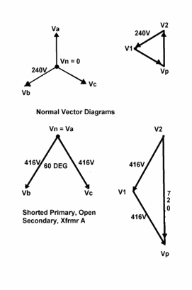
Here are some diagrams to help visualize this problem.

First, we see that normal diagrams for a wye-delta config with an open primary neutral and a balanced load. And, to save our brains, let us assume that the turns ratio is 1 on all transformers.

Next, let us short N to Va and open the secondary on Tx A.

Now, since N is floating, Vn = Va, and the wye phase voltages are 0, 416 and 416. The phase separation between Vb and Vc is now 60 degrees!

This is illustrated in the next pair of diagrams.
The equilateral triangle we had before is now an isosceles triangle and Vp - V2 = 720V @ - 90.

62207f74.gif


[ September 26, 2005, 08:43 PM: Message edited by: rattus ]
 
Re: Wye - Delta Bank

Rattus,
Ok, this explains it well. Now back to the question when one primary is shorted to the star point that short is reflected on the secondary which means we have a short across the other two windings. So the sum of the voltage across these 2 windings is zero. This means the voltage across the remaining indiviual windings are equal and opposite. their magintude should be 416 v with opposite polarity. Does this make sense? if not then how did we get zero volt on each individual winding?
 
Re: Wye - Delta Bank

Basra, note that I assumed that the secondary of TX A was open. This allows 720V across the open secondary.

If the secondary is not open, then the reflected load appears as a short. Assuming that primary voltages are solid, the voltage would be dropped across the internal impedances of the transformers. It is a voltage drop scenario, not a reversal of phase.
 
Re: Wye - Delta Bank

Rattus,
I am not sure I understand you. you are saying that with the shorted load, there will be voltage drop across the other 2 windings and not zero?

Earlier on you had mentioned that the voltages will be zero since the short will be refelected on the secondary of that transformer which shorts out the delta.

please note I am refering to the scenario when the primary is shorted to the star point on one transformer and this short is refelcted on the secondary of that transformer.

My question is what are the magnitudes of the voltages under this condition?
 
Re: Wye - Delta Bank

Originally posted by Basra123:
Rattus,
I am not sure I understand you. you are saying that with the shorted load, there will be voltage drop across the other 2 windings and not zero?

Earlier on you had mentioned that the voltages will be zero since the short will be refelected on the secondary of that transformer which shorts out the delta.

please note I am refering to the scenario when the primary is shorted to the star point on one transformer and this short is refelcted on the secondary of that transformer.

My question is what are the magnitudes of the voltages under this condition?
When I said the the secondary voltage would be zero, that was an approximation. In fact, all three transformers will exhibit internal impedances which will limit the current. Just assume ideal transformers with their internal impedances drawn in series with their secondaries. Then you have three impedances in series--Zb, Za, Zc.

Assuming the short is external, these impedances would be nominally equal. Then assuming fixed line voltages, you would see 240V dropped inside Tx B and inside Tx C leaving 240V across the secondary of Tx A.

This is all very rough, but it should give you a hint of what actually happens. If it does happen, I would clear the area ASAP.
 
Status
Not open for further replies.
Top