Wye - Delta Bank

Status
Not open for further replies.

Basra123

Member
Re: Wye - Delta Bank

Rattus,
How did you get 240? if the one primary is shorted then you will have line to line voltages on each remaining phase which results in 240*1.732=416 on the secondaries of the good transformers and zero on the shorted one.
I guess I am not following you here. what do you mean be external fault?
 

rattus

Senior Member
Re: Wye - Delta Bank

Basra,

Let Za and Zb be the output impedances of Tx B and Tx C. And looking into the secondary of Tx A, we see Za. Za = Zb = Zc.

We now have a simple voltage divider with 720V across it. Whatever the current, the voltage will divide in thirds. One third is across the secondary of Tx A, two thirds are internal to Tx B and Tx C. You only see the 240V across the external lugs. The rest is internal.

Sounds like we need another diagram.
 

rattus

Senior Member
Re: Wye - Delta Bank

Basra, do this:

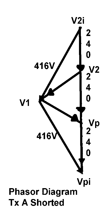
Represent Tx B and Tx C by AC sources of 416V @ 240 and 416V @ 300. Let the internal impedance be 1 Ohm in each transformer.

Connect these sources in series.

The open circuit voltage is 720V @ 270 as shown in the diagram.

Now represent Tx A as a 1 Ohm resistor. This is its internal impedance since the primary is shorted externally.

Now connect Tx A. The current will be,

I = 720V/3Ohms = 240A

The voltage across Tx A is simply,

V = 240A x 1 Ohm = 240V

Again, this is rough, but it should give you the idea.
 

Basra123

Member
Re: Wye - Delta Bank

Rattus,
If I understand you right then the voltages between:

L1 & L2 = 416 (across the center tapped)
L2 & P = 416 (Across the 2nd Tx)
L1 & P = 240 (Across 3rd shorted Tx)

or they are all at 240?
 

rattus

Senior Member
Re: Wye - Delta Bank

Originally posted by Basra123:
Rattus,
If I understand you right then the voltages between:

L1 & L2 = 416 (across the center tapped)
L2 & P = 416 (Across the 2nd Tx)
L1 & P = 240 (Across 3rd shorted Tx)

or they are all at 240?
Basra, they are all at 240V. The 416, 416, 720 phasor diagram is squeezed into a 240, 240, 240 diagram. You can only measure the 240V across Tx A. The other drops are internal to Tx B and Tx C. You cannot probe inside the transformer, you can only compute the internal drops.
 

Basra123

Member
Re: Wye - Delta Bank

Rattus,
Ok, so that means you can measure 240 on the P leg with respect to L1 or L2 and nothing between L1 & L2?

What do you mean by saying the voltages 240 on the other 2 transformers are internal to the transformer and won't show up on the secondary leads? if it is internal then it has to be across the secondary windings and the ends of the windings are extended outside so you can measure it otherwise where else it would go?
 

rattus

Senior Member
Re: Wye - Delta Bank

Basra,

In reality, the transformer impedance is distributed throughout the primary and secondary, but a transformer can be modeled as an AC source and a lumped series impedance. That requires 3 lugs, but only 2 are brought out. You do not have access to that imaginary internal lug, therefore you cannot put a voltmater across the internal impedance.
 

rattus

Senior Member
Re: Wye - Delta Bank

Basra, look at this diagram. Note that the voltages V2i and Vpi are buried inside the transformer. All you can measure externally are V21, V2p, and V1p.
vectors2.gif


[ September 29, 2005, 05:25 PM: Message edited by: rattus ]
 

Basra123

Member
Re: Wye - Delta Bank

Rattus,

Thanks for the diagram. under this assumption then these voltages v21, v1p, v2p are no different from their original values prior to the shorted primary !! under normal operation, we get these values. So the short really didn't amount to nothing here. Correct?
 

rattus

Senior Member
Re: Wye - Delta Bank

Basra,

Wrong! These are rough calculations, and the transformers are overloaded. If the breakers have not popped yet, the transformers are fried. It is just a fluke that the voltages turned out as they did.
 
Status
Not open for further replies.
Top