You are using an out of date browser. It may not display this or other websites correctly.
You should upgrade or use an alternative browser.
You should upgrade or use an alternative browser.
Y Y Transformer Grounding
- Thread starter nkbhinge
- Start date
- Location
- New Jersey
- Occupation
- Journeyman Electrician (retired)
Even with a Wye primary you do not connect a neutral to it and you do not ground the primary H0. (fixed error)
Last edited:
- Location
- New Jersey
- Occupation
- Journeyman Electrician (retired)
Sorry yes primary H0. I'll make the correction thank you.Did you mean primary H0?
So basically, if I have a service disconnect switch before the transformer, I have a MBJ at the service disconnect switch. From this service disconnect switch, I bring 3 Lines, and EGC? No neutral? And at the transformer primary, do not connect neutral to ground? But do it at transformer secondary with SBJ? Does this seem to make sense? If yes, why then it is called Yg-Yg? Sorry for too many questions.
Joethemechanic
Senior Member
- Location
- Hazleton Pa
- Occupation
- Electro-Mechanical Technician. Industrial machinery
Are you talking about the "WYE-WYE Always Tie" thing?
wwhitney
Senior Member
- Location
- Berkeley, CA
- Occupation
- Retired
I believe that only applies when the transformer has a set of delta windings on it (secondary or tertiary). As that would enforce the condition that the sum of the primary L-N voltages is 0, by drawing extra current on the primary if necessary. Which is a problem if the primary system at the transformer is not perfectly voltage balanced.Even with a Wye primary you do not connect a neutral to it
As to the Yg-Yg question, the primary wye system's neutral would be earthed only at its source, not at this transformer. The secondary wye could be installed as an SDS, in which case you connect the secondary's neutral to a GEC to earth it, and install an SBJ on the secondary side. Or it could be grounded directly by connecting the primary neutral to the secondary neutral, making it not an SDS. The latter has a longer fault clearing path for ground faults (relying on the MBJ/SBJ on the primary wye system). Either way the primary and secondary neutrals get interconnected, either through the GES for the SDS, or directly.
Cheers, Wayne
Joethemechanic
Senior Member
- Location
- Hazleton Pa
- Occupation
- Electro-Mechanical Technician. Industrial machinery
I'm pretty sure even ungrounded, without a neutral you need to tie the primary and secondary H0-X0 to keep the voltages stable.I believe that only applies when the transformer has a set of delta windings on it (secondary or tertiary). As that would enforce the condition that the sum of the primary L-N voltages is 0, by drawing extra current on the primary if necessary. Which is a problem if the primary system at the transformer is not perfectly voltage balanced.
As to the Yg-Yg question, the primary wye system's neutral would be earthed only at its source, not at this transformer. The secondary wye could be installed as an SDS, in which case you connect the secondary's neutral to a GEC to earth it, and install an SBJ on the secondary side. Or it could be grounded directly by connecting the primary neutral to the secondary neutral, making it not an SDS. The latter has a longer fault clearing path for ground faults (relying on the MBJ/SBJ on the primary wye system). Either way the primary and secondary neutrals get interconnected, either through the GES for the SDS, or directly.
Cheers, Wayne
That y-y always tie, goes back a long time in my schooling, so I may be remembering it wrong. I remember "Alley Cat Bad Dog" though and my resistor color codes, so school wasn't a total waste
D. Castor
Senior Member
- Location
- Port Angeles, Wash
- Occupation
- Electrical Engineer
I don't think it is advisable to leave the primary Y totally ungrounded if the secondary Y is grounded unless there is a tertiary delta winding in the transformer to supply current for secondary ground faults.Even with a Wye primary you do not connect a neutral to it and you do not ground the primary H0. (fixed error)
Joethemechanic
Senior Member
- Location
- Hazleton Pa
- Occupation
- Electro-Mechanical Technician. Industrial machinery
Here is what I remember about Y-Y connections. If H0 and X0 aren't tied and you have a low impedance fault to P-P or P-N/G your voltage will spike on the phase or phases that are not involved in the fault.
- Location
- New Jersey
- Occupation
- Journeyman Electrician (retired)
You might be correct. Can you explain this further as it relates to the OP?I don't think it is advisable to leave the primary Y totally ungrounded if the secondary Y is grounded unless there is a tertiary delta winding in the transformer to supply current for secondary ground faults.
wwhitney
Senior Member
- Location
- Berkeley, CA
- Occupation
- Retired
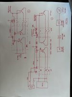
In case 2, you would not both install an SBJ and directly connect the primary neutral to the secondary neutral. That puts primary neutral current on the grounding system, as it puts the SBJ in parallel with the MBJ. So you do one or the other, to get an SDS or not.Case 2, I am bringing neutral, tying H0 and X0 together
Also, in the case 2 diagram, what you have labeled an SSBJ is just the EGC, same as case 1.
I'm not 100% clear on whether and how case 1 would work, but suspect it would give you unstable secondary L-N voltages when you have L-N loads.
Cheers, Wayne
If its not an SDS, then a new system is not 'created' so would the ECG and Neutral of entire fault clearing path of the 208 'side' not need to be sized to minimum size per 250.122 for the 208 side? this would in effect be a TN-S - TN-S wye.As to the Yg-Yg question, the primary wye system's neutral would be earthed only at its source, not at this transformer. ... /... it could be grounded directly by connecting the primary neutral to the secondary neutral, making it not an SDS. The latter has a longer fault clearing path for ground faults (relying on the MBJ/SBJ on the primary wye system). Either way the primary and secondary neutrals get interconnected, either through the GES for the SDS, or directly.
wwhitney
Senior Member
- Location
- Berkeley, CA
- Occupation
- Retired
Presumably your first writing of 208 was meant to be 480, and I am responding as such.If its not an SDS, then a new system is not 'created' so would the ECG and Neutral of entire fault clearing path of the 208 'side' not need to be sized to minimum size per 250.122 for the 208 side?
That is an interesting point, as the secondary depends on the MBJ from the primary for ground fault clearing. And while this is certainly true from a technical perspective, I wonder if the NEC is sufficiently clear about this anywhere.
In the diagram shown this would not be a big change, as the transformer is supplied directly from the service disconnect with the MBJ.
Cheers, Wayne
synchro
Senior Member
- Location
- Chicago, IL
- Occupation
- EE
If its not an SDS, then a new system is not 'created' so would the ECG and Neutral of entire fault clearing path of the 208 'side' not need to be sized to minimum size per 250.122 for the 208 side? this would in effect be a TN-S - TN-S wye.
Presumably your first writing of 208 was meant to be 480, and I am responding as such.
That is an interesting point, as the secondary depends on the MBJ from the primary for ground fault clearing. And while this is certainly true from a technical perspective, I wonder if the NEC is sufficiently clear about this anywhere.
In the diagram shown this would not be a big change, as the transformer is supplied directly from the service disconnect with the MBJ.
Case 2 without the second bonding jumper should behave electrically the same as a wye autotransformer when under a secondary L-G fault. The EGC of course would conduct the full fault current. And the neutral between the MBJ and transformer would conduct (1- 120/277) = 0.567 of the fault current, both in case 2 and with an autotransformer. This compares with 120/277 = 0.433 of the fault current that is transformed back to the line input of the transformer. And so there's not as much of an increase in the fault current on the neutral as on the EGC.
I'm not sure if there's language in the NEC on the size of the EGC specific to autotransformers. But it makes sense that the EGC would be sized for the transformer secondary fault current all the way back to the MBJ in case 2 (without the second bonding jumper).
The neutral fault current mentioned above assumes that there is 0 degrees phase shift between primary and secondary L-N voltages (vector group Yy0 ). This is normally the case. But if in the unusual case of vector group Yy6 with 180 degree phase shift, on the neutral conductor the fault current appearing on the primary would add to the fault current on the secondary instead of subtracting. And so the fault current on the neutral between the MBJ and transformer would be 1.433 times the secondary L-G fault current.
D. Castor
Senior Member
- Location
- Port Angeles, Wash
- Occupation
- Electrical Engineer
A Y-Yg configuration can lead to overvoltages. Here's an excerpt from an old Western Protective Relay Conf paper:You might be correct. Can you explain this further as it relates to the OP?
"As listed in IEEE C57.105-1978 [4] , Y-YG connection is not recommended for three
phase transformers. Y-YG connection is incapable of furnishing a stabilized neutral, and
its use may result in phase-to-neutral overvoltage on one or two legs as a result of
unbalanced phase-to-neutral load."
In 1000V or less systems;
what I don't get is what a wye on the primary side offers?
Why not just do a delta : wye
I do get that people like wye secondary and I see many designs moving legacy single voltage delta to wye secondaries (like 240Y139) for VFD's etc. as it eliminates redundant 'isolation' transformers.
Why the wye wye?
Joethemechanic
Senior Member
- Location
- Hazleton Pa
- Occupation
- Electro-Mechanical Technician. Industrial machinery
I was wondering that tooWhy the wye wye?
Are they trying to avoid the phase shift of a delta wye? What unique thing is trying to be achieved by a Y-Y? And this is supposed to be a SDS?
Last edited: