How does current flow in a circuit?

Status
Not open for further replies.

mivey

Senior Member
Im just curious... This n-1 variables, are voltage or currents? or what?
Currents
not always, if you have done this calc many times, at the end you will not have to make the assumption of the currents.

[Ybus]*[Vbus]=[Ibus]
We are discussing using three current values to calculate a fourth.
current sense = from where to where does the current flows.
Yes. The term sense is used to indicate which of two opposite directions is used.
 

mivey

Senior Member
Without stipulating the sense of the other currents, you can't resolve the nth current.
For example:

A black box has four conductors connected to the rest of the circuit. The following instantaneous current measurements were obtained:
5.00<251.00 deg
8.00<103.00 deg
7.00<40.00 deg
Summation produces 7.81< 75.66 deg

Since you do not know the sense of the three measurements you do not know if you have the correct answer. You could easily have:
5.00<71.00 deg
8.00<103.00 deg
7.00<40.00 deg
where summation produces 17.80< 73.04 deg

or you could have:
5.00<71.00 deg
8.00<283.00 deg
7.00<40.00 deg
where summation produces 8.91< 9.25 deg

etc ...
 
I am a new member and cannot find where to post a new thread so hopefully someone can instruct me on this?

In the meantime I have a query which is:

When connecting a single phase load across 2 phases of a 208/120 3 phase 4 wire system what is the actual current drawn in each of the 2 phases?
If for example I had an appliance that had a full load current of 20A would the current be 10A on each of the the two phases connected. If it was phase to neutral I know that theoretically it would be 20A on the phase conductor with no current on the neutral, but what about phase to phase?

The current flow will obey Ohm's law. In other words if your single phase equipment is rated 120V and you connect it to 208V a resistive load will draw more current. If the applicance is rated 20A then you will have 20A 'flowing' in each leg. Likewise a 3 phase equipment will 'draw' it's nameplate current in each leg.

Remember; a neutral is just a phase that is forced to, referenced to ground.
 

Smart $

Esteemed Member
Location
Ohio
Stone-thrower.:grin: It was you who suggested that someone might get confused by the other forms of KCL. My response was that a competent person would not be trying to use a tool without proper instruction. It was you who wanted to start labeling people as incompetent because they did not possess all knowledge. I think labeling someone as incompetent requires a higher burden of proof.

There is nothing wrong with not knowing something. There is something wrong with refusing to admit it, and there is something wrong with using a tool without being versed in its operation. That is when I would say someone is acting incompetently.
You are a contradiction in and of yourself ;)

One of two opposite directions in which a line, surface, or volume, may be supposed to be described by the motion of a point, line, or surface.You can't obtain the "proper" phase angles without assigning a direction to the n-1 currents measured.
That is correct. And who said the following:
... In relaying and power systems, it is common to look at the current direction to be direction of flow in the positive 1/2 cycle using conventional notation.
As such, are we taking into consideration whether the current of the other branches is incoming or outgoing at that particular time for the sake of such notation? No. Our only concern is the point in time (albeit the rotational or cyclic angle) at which the positive peak occurs relative to a timing or angle reference.

Without stipulating the sense of the other currents, you can't resolve the nth current.For example:

A black box has four conductors connected to the rest of the circuit. The following instantaneous current measurements were obtained:
5.00<251.00 deg
8.00<103.00 deg
7.00<40.00 deg
Summation produces 7.81< 75.66 deg

Since you do not know the sense of the three measurements you do not know if you have the correct answer. You could easily have:
5.00<71.00 deg
8.00<103.00 deg
7.00<40.00 deg
where summation produces 17.80< 73.04 deg

or you could have:
5.00<71.00 deg
8.00<283.00 deg
7.00<40.00 deg
where summation produces 8.91< 9.25 deg

etc ...
I believe your premise is in error. Instantaneous measures are always at 0?. While you are considering that statement, let me give you an example which doesn't require any "current sense" to obtain a result:

The system configuration is 208Y/120 3? 4W.

Connected to this system, we have a mwbc with the following loads:
Line 1 (?A) is 10A, 0.9pf
Line 2 (?B) is 15A, 0.85pf
Line 3 (?C) is 20A, 0.95pf​

Determine the neutral current for this mwbc.​

FWIW, the answer is 11.62A. Though we generally have little concern with the phase angle of the neutral, if we need to know and we use the convention V_A@0?, V_B@120?, V_C@240?, then the phase angle would be 44.4?.
 

Mayimbe

Senior Member
Location
Horsham, UK
Instantaneous measures are always at 0?.

Sorry Smart $, I know Im not involved in this discussion you are having with mivey. But this statement surprised me, what did you mean by that?

let me see, if I have understand,

Ia = 10*cos(wt)
Ib = 12* cos(wt + 120?)
Ic = 11* cos(wt - 120?)

If at t = 123 sec
I make a meassure of this currents, all of them will be at 0???
 

mivey

Senior Member
You are a contradiction in and of yourself ;)
I know I am, but so am I. :grin:
And who said the following:
A very wise man.
As such, are we taking into consideration whether the current of the other branches is incoming or outgoing at that particular time for the sake of such notation? No. Our only concern is the point in time (albeit the rotational or cyclic angle) at which the positive peak occurs relative to a timing or angle reference.


I believe your premise is in error. Instantaneous measures are always at 0?. While you are considering that statement, let me give you an example which doesn't require any "current sense" to obtain a result:
The system configuration is 208Y/120 3? 4W.

Connected to this system, we have a mwbc with the following loads:
Line 1 (?A) is 10A, 0.9pf
Line 2 (?B) is 15A, 0.85pf
Line 3 (?C) is 20A, 0.95pf
Determine the neutral current for this mwbc.
FWIW, the answer is 11.62A. Though we generally have little concern with the phase angle of the neutral, if we need to know and we use the convention V_A@0?, V_B@120?, V_C@240?, then the phase angle would be 44.4?.
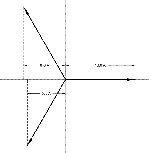
OK I will consider it after I run some errands. But reverse rotation? No leading or lagging notation? At first glance, it looks like you are missing some information.
 

Smart $

Esteemed Member
Location
Ohio
Sorry Smart $, I know Im not involved in this discussion you are having with mivey. But this statement surprised me, what did you mean by that?

let me see, if I have understand,

Ia = 10*cos(wt)
Ib = 12* cos(wt + 120?)
Ic = 11* cos(wt - 120?)

If at t = 123 sec
I make a meassure of this currents, all of them will be at 0???
If you want the instantaneous measures, yes. Your formulas are correct but it is understood (taught or covered previously in your education) that:
Ia<0? = 10*cos(wt)
Ib<0? = 12* cos(wt + 120?)
Ic<0? = 11* cos(wt - 120?)

instantaneouscurrentmeasures.gif
 

Smart $

Esteemed Member
Location
Ohio
But reverse rotation? No leading or lagging notation? At first glance, it looks like you are missing some information.
From your post with no negative angles I assumed you were using reverse rotation. I (traditionally) prefer ?B@-120? (= 240?) and ?C@-240? (= 120?), which simply changes the result to -44.4? (= 135.6?). Sorry about not noting pf leading or lagging. A habit stemming from 99.999% of the pf's I deal with are lagging.
 
Last edited:

Mayimbe

Senior Member
Location
Horsham, UK
I should note that you shouldn't write the formulas as such. I only added the "<0?" for emphassis.

If you want the instantaneous measures, yes. Your formulas are correct but it is understood (taught or covered previously in your education) that:
Ia<0? = 10*cos(wt)
Ib<0? = 12* cos(wt + 120?)
Ic<0? = 11* cos(wt - 120?)

It was not taught or covered previously in my education, but I can see whats your point. I dont understand whats the mean of the graphic. What does this proyections stands for??

If I measure Ia, I will see in the display of the ammeter 10/sqrt(2) the RMS value.

Ib = 12/sqrt(2)

Ic = 11/sqrt(2)
 

mivey

Senior Member
While you are considering that statement, let me give you an example which doesn't require any "current sense" to obtain a result
You still have a current sense. You are using the voltage polarity & power factor to derive the current sense. :roll:
FWIW, the answer is 11.62A. Though we generally have little concern with the phase angle of the neutral, if we need to know and we use the convention V_A@0?, V_B@120?, V_C@240?, then the phase angle would be 44.4?.
Using In+Ia+Ib+Ic=0, we sum the currents and multiply by -1 and In would be 6.07A with an angle of 26.4?
Using In=Ia+Ib+Ic, we sum the currents and In would be 6.07A with an angle of 206.4?
From your post with no negative angles I
assumed you were using reverse rotation. I (traditionally) prefer ?B@-120? (= 240?) and ?C@-240? (= 120?)
That is my preference as well and what I used.

Using In+Ia+Ib+Ic=0, we sum the currents and multiply by -1 and In would be 11.62A with an angle of 315.6?
Using In=Ia+Ib+Ic, we sum the currents and In would be 11.62A with an angle of 135.6?
 

mivey

Senior Member
Note that the difference in the two formulas
In+Ia+Ib+Ic=0
and
In=Ia+Ib+Ic
is the current sense you pick for In. If you choose between these formulas, you are picking a current sense for In.

Using a voltage polarity reference, measurement constraints, etc. means you are making some directional assumptions for the currents whether you realize it or not.
 
Status
Not open for further replies.
Top