Power factor and VA vs Watts

Status
Not open for further replies.

Hameedulla-Ekhlas

Senior Member
Location
AFG
You guys are really arguing apples and oranges. What you say is correct from a statics standpoint, but what the other guys are talking about is from a dynamics perspective, and never the twain shall meet unless you are talking about a DC circuit.

Gunn:

Would you please give some information regarding to apples and oranges and the difference. :grin:
 

ggunn

PE (Electrical), NABCEP certified
Location
Austin, TX, USA
Occupation
Consulting Electrical Engineer - Photovoltaic Systems
Gunn:

Would you please give some information regarding to apples and oranges and the difference. :grin:
Any idiot knows that apples are vectors and oranges are scalars. Did you get your engineering degree through the mail? :grin:
 

Besoeker

Senior Member
Location
UK
You guys are really arguing apples and oranges. What you say is correct from a statics standpoint, but what the other guys are talking about is from a dynamics perspective, and never the twain shall meet unless you are talking about a DC circuit.
What happens in an AC power circuit over a period of 1us isn't a whole lot different to what happens in a DC circuit over that same period.
To that extent at least, it is apples for apples.
 

rattus

Senior Member
No

However I am heartened to see you use the notation v(t) instead of just "v". I was sure I knew what you meant, but for a purist such as your self, it made it look like you could be confusing vectors/phasors with time domain equations.

cf

No confusion at all. Rotating phasors for example are functions of time (time domain) as are v(t), i(t), and p(t). We seldom get into the frequency domain.

Now the values of v(t), i(t), and p(t) are signed numbers with no phase angles attached, therefore they can be neither vectors nor phasors. Therefore, they must be scalars.

The phase angle is imbedded in the trig arguments and does not appear in the values.
 

Smart $

Esteemed Member
Location
Ohio
Instantaneous power is just power. In Watts.
One Volt and one Amp at the same instant is one Watt.
It doesn't matter if the circuit is pure resistance or has reactive components. It is still just 1W.
Even if it was a DC circuit, it would still be 1W.
Suppose you take a very short segment of the waveform I posted in #156. Say 1us at 45deg. At that point you have 1V, 1A, 1W.
It doesn't matter how it got there. It is 1W. Nothing apparent about it.

You guys are really arguing apples and oranges. What you say is correct from a statics standpoint, but what the other guys are talking about is from a dynamics perspective, and never the twain shall meet unless you are talking about a DC circuit.
I believe the issue is even deeper rooted than static vs. dynamic analysis. Even when considering only the value(s) of power(s) at a single point in time (static analysis), the value of reactive and resistive portions still have values. For example, if instantaneous resistive (active) and reactive power(s) can be determined by equation as a function of time then instantaneous values can be determined simply by specifying the time "instant" value and computing. And there is no need to know or determine the slope(s) at this particualr point in time.

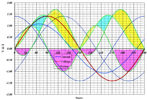
This is why I brought up combined loads. In the following depiction, I have overlayed all three of Besoeker's graphs (as best I could in a short amount of time). The input power peak is fairly normal and centered, while the capacitive load's power peak is skewed left and the inductive load's to the right. Note how for the time periods shaded yellow, the power delivered to the individual load is greater than the input power. The extra power is transferred from the other load (magenta shading). There is only a short duration (cyan shading) where input power is greater than either load, and a very short duration of negative power (not shaded, or accidentally shaded magenta :D).

PFVAW6.gif
 

ggunn

PE (Electrical), NABCEP certified
Location
Austin, TX, USA
Occupation
Consulting Electrical Engineer - Photovoltaic Systems
What happens in an AC power circuit over a period of 1us isn't a whole lot different to what happens in a DC circuit over that same period.
To that extent at least, it is apples for apples.
That's not quite true. In reactive circuits everything is happening because things are changing. As you say, to a static analysis there is no such thing as different kinds of power, although troublesome things like negative impedance fall out of the equations. If you consider a finite slice of time, however, then you must consider not only the state of things but their rates of change, and that's where all the excitement happens.

And BTW, in many AC circuits an awful lot can happen in a microsecond. :D
 

Besoeker

Senior Member
Location
UK
That's not quite true. In reactive circuits everything is happening because things are changing. As you say, to a static analysis there is no such thing as different kinds of power,
My point was about instantaneous values.
Rate of change would thus not be applicable.
 

Besoeker

Senior Member
Location
UK
I believe the issue is even deeper rooted than static vs. dynamic analysis. Even when considering only the value(s) of power(s) at a single point in time (static analysis), the value of reactive and resistive portions still have values.
They don't.
I have no expectation that you will accept that.
You'd have to backtrack and you won't.
 

Smart $

Esteemed Member
Location
Ohio
My point was about instantaneous values.
Rate of change would thus not be applicable.
That is correct. Additionally, a static analysis, strictly speaking, cannot be done on power. Power is a dynamic quality. It is the time rate at which work is performed or energy converted, and both work and energy are time dependent. Neither work nor energy exist in an instant. Some interval of time must take place, no matter how short, for power to exist.
 

rattus

Senior Member
How can you?

How can you?

They don't.
I have no expectation that you will accept that.

Bes, How can you maintain this position when the equation for p(t) clearly shows the real and reactive components of the vi product?? And, how do you explain the plots that provide graphic proof??
 

K2500

Senior Member
Location
Texas
...there are probably more lurkers (or there was) that have no idea what the math is all about... yet they may understand a pictorial representation, or perhaps grasp a little better understanding.

There is at least one left.


Instantaneous power is just power. In Watts.
One Volt and one Amp at the same instant is one Watt.
It doesn't matter if the circuit is pure resistance or has reactive components. It is still just 1W.
Even if it was a DC circuit, it would still be 1W.
Suppose you take a very short segment of the waveform I posted in #156. Say 1us at 45deg. At that point you have 1V, 1A, 1W.
It doesn't matter how it got there. It is 1W. Nothing apparent about it.


Purely reactive loads(ideal) would result in a 90 degree lead/lag, preventing the appearance of real power, since instantaneous voltage would not concur with instantaneous current.
Then the values obtained from any instance with overlap would be a reflection of real power.
Is this at least partially correct?

I ask if partially correct because, during this instance with voltage at peak positive and current at peak negative, the resultant power is negative.
I have no concept of negative power, except to say it indicates to me that it is power consumed by the source.
 

Besoeker

Senior Member
Location
UK
That is correct. Additionally, a static analysis, strictly speaking, cannot be done on power. Power is a dynamic quality. It is the time rate at which work is performed or energy converted, and both work and energy are time dependent. Neither work nor energy exist in an instant. Some interval of time must take place, no matter how short, for power to exist.
Incorrect. Rate does not require the passage of time.
 

Besoeker

Senior Member
Location
UK
Bes, How can you maintain this position when the equation for p(t) clearly shows the real and reactive components of the vi product?? And, how do you explain the plots that provide graphic proof??
My plots show instantaneous current, voltage, and power.
You cannot show a magnitude v time plot of real and reactive components over one cycle.
For example, the plot in post #156 shows one cycle of a purely reactive load, capacitance in this case. It shows how the the power varies over that one cycle. The average over the whole cycle is zero. That's why there is no real power. But, at any instant during that cycle, the power may have positive, negative, or zero values.
 

Smart $

Esteemed Member
Location
Ohio
Incorrect. Rate does not require the passage of time.
True... but power is dependent on values which do: work and conversion of energy. I'm not saying you cannot evaluate p at some specific t. I'm saying it is conditional upon Δt>0.

8f5a95a95ef23ece175e2c1f590b9802.png
 

Smart $

Esteemed Member
Location
Ohio
My plots show instantaneous current, voltage, and power.
No one is disputing this in simplistic terms.

You cannot show a magnitude v time plot of real and reactive components over one cycle.
Why not?

For example, the plot in post #156 shows one cycle of a purely reactive load, capacitance in this case. It shows how the the power varies over that one cycle. The average over the whole cycle is zero. That's why there is no real power. But, at any instant during that cycle, the power may have positive, negative, or zero values.
No one is disputing this (in your terms).

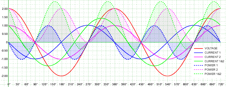
But when there is a resistive load added to say your capacitive load, the instantaneous power changes. In the case of the loads being parallel, the power "input" is portioned to each load. All three—input, resistive load, and capcitive load—can be evaluated and plotted separately. As such, it can be determined that the equation for the input power is equal to the equation for the resistive load added to the capacitive load's equation.

Also note the peak instantaneous power of the three is at different points in time. The input instantaneous power's peak is somewhere between the capacitive load's and the resistive load's. When we analyze this shift in timing, we find the capacitive and resistive components of the input instantaneous power are related to the amplitude of the components' current and the shift between the each of the three power waveforms.

PFVAW7.gif


I'm gonna stop here, for I don't want to waste my time typing on deaf-eared eyes... continuation is dependent on your reply :roll:
 
Last edited:

Smart $

Esteemed Member
Location
Ohio
There is at least one left.
Glad to hear it :)

Purely reactive loads(ideal) would result in a 90 degree lead/lag, preventing the appearance of real power, since instantaneous voltage would not concur with instantaneous current.
Then the values obtained from any instance with overlap would be a reflection of real power.
Is this at least partially correct?

I ask if partially correct because, during this instance with voltage at peak positive and current at peak negative, the resultant power is negative.
I have no concept of negative power, except to say it indicates to me that it is power consumed by the source.

I'm uncertain what you mean by...
Then the values obtained from any instance with overlap would be a reflection of real power.
... especially the overlap part. Perhaps where the areas under the voltage and current waveforms are concurrent? If so, no. The only readily discernable sign of real power (in the conventional, power-engineering sense ;)) is current other than zero when voltage is at its peak (in sinusoidal waveform analyses).

Regarding your last comment... Voltage at its positive peak while current is at its negative peak simply does not occur. That would be the current leading or lagging by 180?. Ideal reactive components' current lead or lag by 90?. When there is a combination real and reactive load, the current shift is somewhere between +90? and ?90?. However, yes, there are instances where the vi product is negative, and thus power is negative. This can be likened to lifting a block in the air. Work was performed and the power of this occurence is the rate at which the work happened. If you then drop the block, this can be considered negative power because it is work undone, and the power would be the rate at which the work was undone.
 

rattus

Senior Member
My plots show instantaneous current, voltage, and power.
You cannot show a magnitude v time plot of real and reactive components over one cycle.
For example, the plot in post #156 shows one cycle of a purely reactive load, capacitance in this case. It shows how the the power varies over that one cycle. The average over the whole cycle is zero. That's why there is no real power. But, at any instant during that cycle, the power may have positive, negative, or zero values.

Strictly speaking, magnitude is a constant, and such a plot would be useless. I don't understand why one would want to do this anyway.

But we can plot instantaneous values of real and reactive power, and in so doing we separate the real and reactive portions of the vi product which you say is impossible. Just like you plotted reactive power for the cap, we can plot real power on the same graph.
 
Status
Not open for further replies.
Top