Single Phase Theroy

Status
Not open for further replies.

mivey

Senior Member
If you want to represent this as real-world, then you are stuck with a common-core transformer and you can no longer interject your phase shift and minus sign.
As I have said before, I am looking at the voltage waveforms and their relationships with each other. How they are derived/created/etc is a different issue. The nature of a collection of voltages is what is usually called into question. The questions usually are centered around a question that asks why does a set of voltages look like and exhibit the behavior of one thing but is then called something else.

Where the voltages come from is of interest for some other application issues, but it has little bearing on how we label a collection of voltage sources in the general case. Yes, that is what I said, even for most of our applications the voltages are usually independent enough for what we are doing to consider them as individual sources.

Anyway, the core is no restriction on shifts and signs. We have a real world application where we take a two-phase system of voltages and use two fluxes through two transformer cores to produce a three-phase system of voltages (Scott connections). Again, the method of creation is not the focus but rather the voltage waveforms and their relationships to each other.

An Open-Wye Open-Delta real world bank also uses two cores to convert from a system of two phase-displaced voltages to three phase-displaced voltages.

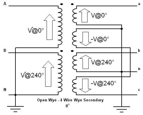
Another real world application is the Open-Wye to 4-wire Wye connection. It uses two cores but takes advantage of the center-tap and the real world fact that the negative signs are also physical realities. It uses these real world minus signs to create a real world set of three phase-displaced voltages.

I have a power supply on my workbench right now that could have used a center-tapped transformer. At the time I built it, I did not have the transformer I needed on hand so I used two individual transformers instead of just one. The fact that I used two cores does not mean that the single core application was not real. The reverse is also true: Had I used one core, it would not mean the case of using two cores was not a real-world application.

So, these are not just hypotheticals but physical realities. Whether or not we are actually using them at this very moment does not mean they fall into the world of fantasy.
The people you are misleading in these threads have the right to know that you are not referring to real-world applications.
There is no misleading intended. I have said it is perfectly fine for someone to memorize the list of names we use. I am not on a campaign to change those names either. But, for those that want to move beyond just memorizing a list of specific conventional system names, I am only trying to help them get a better understanding of the systems from the standpoint of the general case. I think I have been more than up-front about my intentions.

If the systems under discussion can be built then they are real. These are not some kind of Escher drawing or some kind of illusion. They are not some theory that looks good but can't really be proved. Even if you have not personally put your hand on one, they are physical realities.

I didn't notice this at the time of my previous posting, but nevertheless this is what should be strongly pointed out to those reading this thread.
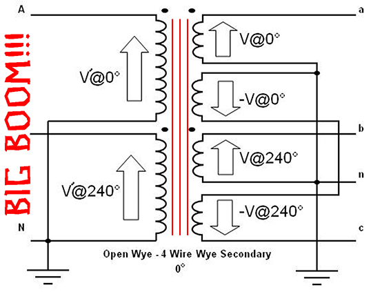
I have tried to make that point many times. For the purposes of identifying a system of voltages, I am not concerned with where they came from because as long as they are voltage sources (which they essentially are), the only real issue is the relationships they have with each other.

The whole basis of this discussion is that you are dealing with non-real-world applications with isolated secondaries and isolated primaries. If either one of which is linked, then you can no longer interject your time shift.
Not true. See above.
 
Last edited:

Rick Christopherson

Senior Member
Mivey, you and Rattus are the two primary proponents of this discussion that have lead to such long discussions spanning several years, so right or wrong, I do lump you two together. This stands to reason, as you two do generally say the same things. Granted, every once in a while, you do use a little more caution in your wording that Rattus does.
In other words:

The voltages, V1n and V2n, in a 120/240V 1-phase sytem are separated by 180 degrees.

I said V1n and V2n are separated by 180 degrees. This is easily demonstrated with a dual channel scope.

We call the 180? system single-phase.

In other words, by convention we call the 180? system single-phase.
Rattus emphatically states that the two voltages are 180 degrees out of phase. You refer to the 120/240 system as the “180? system”.

So I do rightfully lump you two together in this discussion as grossly misleading the readers of this (these) thread(s). Granted, I do give you some credit for periodically mentioning the rarely spoken need for isolated cores and sources before a time delay can be interjected into the definition of a system.

The people you are misleading in these threads have the right to know that you are not referring to real-world applications.
If the systems under discussion can be built then they are real.
Herein lies the source of the misinformation you are presenting. While a 180? system can very easily be built, it is not the “real world” system that we encounter in our day-to-day activities. When you refer to this “180? system” as “real world”, you imply that it is the same single-phase 120/240 system we see every day.

Yes, a “180? system” can be built in real life, but it is not the 120/240V system powering our homes and offices. Yes, I know that you know why this is true, but most of the readers here, including Rattus, may not understand why you cannot have this 180? time shift on a magnetically or electrically coupled system.

You are well within your bounds to analyze the system using a 180? time shift if you so choose, but defining the system as containing a 180? time shift is wrong.
 
Last edited:

mivey

Senior Member
Granted, I do give you some credit for periodically mentioning the rarely spoken need for isolated cores and sources before a time delay can be interjected into the definition of a system.
Only if we do not use the method of subtraction to combine the fluxes to send them through a single core. The point you are missing is that as far as steady-state voltages are concerned, the negative voltage is the same result as a time shift or a phase difference. But a trivial point anyway as I am focusing on the voltages on the other end, not how the system of voltages was created. The load does not really care about the method of creation as it is only concerned about getting the voltages it needs.

Herein lies the source of the misinformation you are presenting. While a 180? system can very easily be built, it is not the ?real world? system that we encounter in our day-to-day activities. When you refer to this ?180? system? as ?real world?, you imply that it is the same single-phase 120/240 system we see every day.

Yes, a ?180? system? can be built in real life, but it is not the 120/240V system powering our homes and offices.
We do not use two separate cores, but the secondary voltages we can get from either system will be exactly the same. Again, I am focusing on the system of voltages, not how they were created.

Yes, I know that you know why this is true, but most of the readers here, including Rattus, may not understand why you cannot have this 180? time shift on a magnetically or electrically coupled system.
Again, the flux used for creation is a different issue.

You are well within your bounds to analyze the system using a 180? time shift if you so choose, but defining the system as containing a 180? time shift is wrong.
I am saying the system of voltages can represent either type of supply. I don't really care what type of supply got me here, I am just discussing how many supplies our system of voltages can represent. If a load wants a 120@0? & 240@? supply OR a 120@0? & 120@180? supply, our system of voltages will represent either type supply.

Again, the focus is not on the method of creation, but the voltage waveforms themselves and the relationships they have with each other. These voltage sources can be created in many different ways, but regardless of the method, the end result would be the exact same voltage waveforms.

Whether we use V1 and -V1 or V1 and V1@180?, there is no difference. Plot out the values and you can see it for yourself:

For a 120 volt 60 hz waveform, let source V1 = |Vmax|*cos(ωt) = 120*sqrt(2)*cos(377*t):
At t=0.00000s (0.0 deg), V1=169.71
At t=0.00833s (3.0 deg), V1=169.47
At t=0.01667s (6.0 deg), V1=168.78
...
At t=0.48333s (174.0 deg), V1=-168.78
At t=0.49167s (177.0 deg), V1=-169.47
At t=0.50000s (180.0 deg), V1=-169.71
At t=0.50833s (183.0 deg), V1=-169.47
At t=0.51667s (186.0 deg), V1=-168.78


Let source V2 = -V1 = -|Vmax|*cos(ωt) = -120*sqrt(2)*cos(377*t):
At t=0.00000s (0.0 deg), V2=-169.71
At t=0.00833s (3.0 deg), V2=-169.47
At t=0.01667s (6.0 deg), V2=-168.78
...
At t=0.50000s (180.0 deg), V2=169.71
At t=0.50833s (183.0 deg), V2=169.47
At t=0.51667s (186.0 deg), V2=168.78

As I stated in my previous post, the use of the negative voltage is actually used in a real world transformer connection to take an open wye set of two phase-displaced voltages to produce a 3-phase wye set of voltages. It does this by using the negative voltages from 1/2 of a center-tapped winding. This negative voltage is really there and we do not have to provide a second isolated core for this to be valid or used in a real-world application. This negative voltage is simply a physical reality, not just some math trick. If it were just a trick, we would not get the 4-wire 3-phase wye that is used in the real world. See the following utility transformer diagram for clarification:

OpenWyeto4WireWyeVoltages.jpg


As you can see, our source has the 0? voltage (voltage A) and the 240? voltage (voltage B) but is missing the 120? voltage. On the secondary side, we have our a & b voltage by using the same orientation as the primary. We use the negatives of the center-tapped secondary voltages to get the c voltage = -V@0? -V@240? = V@120?. The load does not care that we only used two fluxes, and for the purposes of identifying the system of voltages, neither do I.
 

glene77is

Senior Member
Location
Memphis, TN
Mivey and Rattus,
Go to it!
I have followed your responsive postings for several years, and always gain some insight into the wonderful world of electrical science. Sometimes I hear the electrician speaking, sometimes the physicist, sometimes the engineer, sometimes the mathmatician, but from whatever perspect the discussion is carried out, there is good experience being presented.
 

mivey

Senior Member
Mivey and Rattus,
Go to it!
I have followed your responsive postings for several years, and always gain some insight into the wonderful world of electrical science. Sometimes I hear the electrician speaking, sometimes the physicist, sometimes the engineer, sometimes the mathmatician, but from whatever perspect the discussion is carried out, there is good experience being presented.
Thank you. Good to know someone is reading objectively. I like coming here as it makes you think and is a good place to work on communication. I learn a lot and it helps keep me current.
 

Rick Christopherson

Senior Member
But a trivial point anyway as I am focusing on the voltages on the other end, not how the system of voltages was created.
Oh to the contrary. This thread has been about the system, not analyzing the loads. Your discussion is knowingly misleading in this respect, especially when you refer to the systems as a 180? system. You and Rattus are taking your chosen method of analysis and using it to define the system.
As I stated in my previous post, the use of the negative voltage is actually used in a real world transformer connection......
Again, you are trying to deliberately mislead the readers of this thread. Why are you showing a 3-phase system when the discussion is about single phase? Can you not win an argument without deception? Stick to the facts of a standard 120/240 volt system please.
 

Rick Christopherson

Senior Member
Oh by the way, just in case there are those that don't fully pick up on why your 3-phase diagram example is so deceptive to the typical reader of this thread, I put the critical and missing piece back into your diagram. :grin:

BigBoom.jpg
 

mivey

Senior Member
Your discussion is knowingly misleading
...
Again, you are trying to deliberately mislead the readers of this thread.
...
Can you not win an argument without deception?
The theatrics do nothing to support your point. I think most of our readers are intelligent enough to use the facts to evaluate the posts. Perhaps it would be better to stick to the facts unless the rest is just for entertainment value. JMO.


Oh to the contrary. This thread has been about the system, not analyzing the loads. You and Rattus are taking your chosen method of analysis and using it to define the system.
Incorrect. Referring to the OP, the question was posed about who was right, the OP or the teacher. My answer has been that they were both correct.

If the question had specifically been "what kind of transformer is the center-tapped one that provides 120/240?" then the answer would be simple: it is a single-phase transformer.

The OP discussed both the voltages and the transformer. The transformer is single-phase. We call the voltages single-phase, and they are. But the transformer secondary voltages are also those we would get from a system of voltages with 0? and 180? angles. We don't use the name two-phase because the waveforms are already labeled as single-phase and it fits almost everything we do. Also, the system label "two-phase" has traditionally been reserved for the quarter-phase system.

If you think this thread is about the transformer alone or the primary with only one ungrounded conductor, then accept that I call those single-phase and just quit reading the rest of the thread because we are in agreement on those two and have nothing to debate.

Why are you showing a 3-phase system when the discussion is about single phase?
The open-wye example went to refute your premise that to have the minus sign you need separate cores. You also make the erroneous statement that there were no real-world applications that made use of this minus sign.

I agree that we don't need it for the 120/240 supply since we don't bring in two phase-opposed primaries. It makes no economic sense to create the 120/240 that way in a utility-type scenario. I doubt it would ever happen except in a small circuit.

But that does not mean the phase-opposed system can't be represented by the waveforms we have at the secondary level.

Stick to the facts of a standard 120/240 volt system please.
I have stated the facts. The simple truth of the matter is that the facts extend beyond the specific device upon which we can readily, physically put our hands (i.e., the one outside our building).

When looking at a system of voltages and their relationships to each other, the facts extend beyond the primary voltage of the deriving transformer, or one particular transformer configuration, or whatever means is used to create those voltages.
 

mivey

Senior Member
Oh by the way, just in case there are those that don't fully pick up on why your 3-phase diagram example is so deceptive to the typical reader of this thread, I put the critical and missing piece back into your diagram. :grin:
I don't see where that adds anything significant. Care to elaborate on the deception? Maybe your missing piece is like the missing part from Games You Can't Lose by APC :grin: :

Rabbit.jpg
 

Rick Christopherson

Senior Member
Incorrect. Referring to the OP, the question was posed about who was right, the OP or the teacher. My answer has been that they were both correct.
When I asked my apprenticeship teacher he started drawing a picture of two sine waves 180? apart. And insisted it really was two distinct phases.
Then your answer is wrong. You cannot have a time differential in a center-tapped secondary driven by a single primary source. This is the same reason why your 3-phase example blows up when you add the common core between the phases. The commonality precludes the time shift.

But the transformer secondary voltages are also those we would get from a system of voltages with 0? and 180? angles.
As I have already credited you, you are very careful with your words. However, the average reader of this thread is not going to notice your lawyer-like word usage, and that is what makes your statements so deceptive to the forum.

What you state is correct. What the typical reader infers from your words is not correct--and that is why it is deceptive.

We are talking about the real 120/240 volt systems we deal with every day in our homes and offices. Without using your legalese language, can you or can you not get 0? and 180? voltage sources from the same every-day system. I am not asking if you can get waveforms that look like 0? and 180?; I am asking if you can get actual waveforms that are 0? and 180?.

The answer is no, because the commonality of the source precludes it.

I agree that we don't need it for the 120/240 supply since we don't bring in two phase-opposed primaries. It makes no economic sense to create the 120/240 that way in a utility-type scenario. I doubt it would ever happen except in a small circuit.

But that does not mean the phase-opposed system can't be represented by the waveforms we have at the secondary level.
I never said a phase-opposed system couldn?t exist, but you?re not going to find it on the pole outside your house or anyone else?s house for that matter.

You and Rattus are off on your bunny hunt based on this phase-opposed system that doesn?t exist on the U.S. power grid.
Yes, the bunny was funny, and it made me laugh out loud.
laughing1.gif
 

winnie

Senior Member
Location
Springfield, MA, USA
Occupation
Electric motor research
We are talking about the real 120/240 volt systems we deal with every day in our homes and offices. Without using your legalese language, can you or can you not get 0? and 180? voltage sources from the same every-day system. I am not asking if you can get waveforms that look like 0? and 180?; I am asking if you can get actual waveforms that are 0? and 180?.

The counterpoint, which has been made many times over, is that for a single frequency system, 0? and 180? doesn't simply 'look like' 0? and its inversion; the two are _indistinguishable_ and completely _equivalent_.

Since there is no way to distinguish between the two descriptions, you cannot say that one is more 'actual' than the other.

If, for the purpose of a particular analysis, it is more convenient to use 0? and 180?, then it is completely correct to do so.

At the same time, it is essential to understand that different sources in the real world will actually have different characteristics. A real transformer or generator will produce an imperfect sine wave, and therefore we don't have a single frequency system. In such a system there may be discernible differences between time delay and inversion. But once you are looking at non-linear aspects of the transformer and various parasitic frequencies being introduced, then you also need to look at possible different flux coupling to the different halves of the transformer...making one half of the common center tapped secondary not necessarily a simple inversion of the other half.

-Jon
 

K8MHZ

Senior Member
Location
Michigan. It's a beautiful peninsula, I've looked
Occupation
Electrician
Question for those that think 120/240 is two phase, would we get three phase just by adding another tap on the transformer like was done to go from 240 to 120/240?

If not, what logic is used to get two phase from single phase just by adding a tap?

If so, then why do we go through all the trouble of using phase converters?
 

rattus

Senior Member
Question for those that think 120/240 is two phase, would we get three phase just by adding another tap on the transformer like was done to go from 240 to 120/240?

If not, what logic is used to get two phase from single phase just by adding a tap?

If so, then why do we go through all the trouble of using phase converters?

Sparky, No one to my knowledge is calling this a two-phase system.
 

rattus

Senior Member
Well said!

Well said!

The counterpoint, which has been made many times over, is that for a single frequency system, 0? and 180? doesn't simply 'look like' 0? and its inversion; the two are _indistinguishable_ and completely _equivalent_.

Since there is no way to distinguish between the two descriptions, you cannot say that one is more 'actual' than the other.

If, for the purpose of a particular analysis, it is more convenient to use 0? and 180?, then it is completely correct to do so.

At the same time, it is essential to understand that different sources in the real world will actually have different characteristics. A real transformer or generator will produce an imperfect sine wave, and therefore we don't have a single frequency system. In such a system there may be discernible differences between time delay and inversion. But once you are looking at non-linear aspects of the transformer and various parasitic frequencies being introduced, then you also need to look at possible different flux coupling to the different halves of the transformer...making one half of the common center tapped secondary not necessarily a simple inversion of the other half.

-Jon

Well said Winnie!
 

rattus

Senior Member
Zero has an idea!

Zero has an idea!

It occurs to me that the confusion arises from the fact that some have been taught--correctly--that a single transformer can only provide single phase service, But, the phase shift between V1n and V2n does not constitute a 2-phase system.
 

Rick Christopherson

Senior Member
The counterpoint, which has been made many times over, is that for a single frequency system, 0? and 180? doesn't simply 'look like' 0? and its inversion; the two are _indistinguishable_ and completely _equivalent_.
Yes, they are indistinguishable on a scope, but they are not mathematically equal. An inversion is a minus sign. A phase shift is a time delay.
Since there is no way to distinguish between the two descriptions, you cannot say that one is more 'actual' than the other.
Yes you can, because you cannot get a time shift from a single source transformer. As the other poster commented, you can't get 3-phase by simply adding another secondary because there is no time delay.
If, for the purpose of a particular analysis, it is more convenient to use 0? and 180?, then it is completely correct to do so.
As I have already said:........
You are well within your bounds to analyze the system using a 180? time shift if you so choose, but defining the system as containing a 180? time shift is wrong.

At the same time, it is essential to understand that different sources in the real world will actually have different characteristics. A real transformer or generator will produce an imperfect sine wave, and therefore we don't have a single frequency system. In such a system there may be discernible differences between time delay and inversion. But once you are looking at non-linear aspects of the transformer and various parasitic frequencies being introduced, then you also need to look at possible different flux coupling to the different halves of the transformer...making one half of the common center tapped secondary not necessarily a simple inversion of the other half.
Correct, and this is why you can't define the system as containing a time delay that doesn't really exist. The analysis of the system is probably fine, but defining the system is different than the analysis.

The other posters are using their chosen method of analysis to define the system. That would be the same as saying that you can replace all of the transistors in your computer with their small signal equivalent.
 

winnie

Senior Member
Location
Springfield, MA, USA
Occupation
Electric motor research
Question for those that think 120/240 is two phase, would we get three phase just by adding another tap on the transformer like was done to go from 240 to 120/240?

I would not call a 120/240 system 'two phase'; that is reserved for a specific polyphase system with 90 degree phase angle difference between the phases.

Nor would I call a 120/240 system some other version of 'polyphase'. It is a single phase system.

But I stand by the assessment that there are two _different_ phase angles present. The time relation of these two phase angles is such that they could not be used in a motor to generate a rotating field.

I guess the other side of your question is: for those who think that 120/240 is single phase, where is the logic in getting 'three phase' power just by adding _one_ more transformer? (Related to the original question of the thread.)

My answer: a single phase system has 2 phase angles, so by adding an additional transformer you can get 6 phase angles, which we call three phase.

-Jon
 

winnie

Senior Member
Location
Springfield, MA, USA
Occupation
Electric motor research
I am going to revise my wording, because I agree with Rick on this point:
An inversion is a minus sign. A phase shift is a time delay.

My revision is:
The counterpoint, is that for a single frequency system, a sine wave produced by a 180? delay and a sine wave produced by inversion do not simply look the same, they are _indistinguishable_ and completely _equivalent_.

I agree that there are different methods that will get you to the given output, and that these different methods will have different mechanics, and (given the real world) different flaws. But in the idealized case the _outputs_ are equivalent, and if the outputs are equivalent than for anything which looks only at the output the internal mechanics are irrelevant.

Furthermore, since the outputs are equivalent, I can use either method to create the output for either application. Say I need a time delay of exactly 1/2 cycle; I don't have to invest in a delay line; I can use a simple inversion.

Because the outputs of the different mechanisms are the same (again, in the idealized case), then it is reasonable and correct to use names derived from either mechanism in order to describe these outputs. IMHO it is just as reasonable to say '0? and its inverse' as to say '0? and 180?' to name the legs on a single phase supply.

-Jon
 

rattus

Senior Member
What he said:

What he said:

.

Because the outputs of the different mechanisms are the same (again, in the idealized case), then it is reasonable and correct to use names derived from either mechanism in order to describe these outputs. IMHO it is just as reasonable to say '0? and its inverse' as to say '0? and 180?' to name the legs on a single phase supply.

-Jon

In other words,

-120V @ 0 = +120V@ 180

Either value will provide the same result.

We of course assume pure sinusoids and linear circuit elements. If these assumptions cannot be made, then we cannot use phase angles anyway.

Still single phase though!
 
Status
Not open for further replies.
Top