Rick Christopherson
Senior Member
I've only been reading this thread piece-meal as new postings have been made, but it appears there may still be some confusion with the topic. I think this might be due to some terminology and how we sometimes visualize systems.
The first thing I noticed is that maybe some people are getting hung up on the term "phase shift" or "phase angle". In this particular situation, it might be better to realize that a "phase shift" is simply a "time delay". We call it an angle because we sometimes use phasor diagrams to solve problems, but it is really nothing more than a shift in time. That shift in time is 1/3 of a cycle. Since 1 cycle is 1/60th of a second (at 60 hertz), then 1/3 of that is 1/180th of a second (0.005 sec).
What that means is that when one of our sine waves crosses zero, the next sine wave won't cross zero for another 0.005 seconds. It's been delayed from the first sine wave.
The next thing to realize is that each of the phases in the system is just a single voltage reference. You need two reference points to record a voltage, and our voltmeter is reading just the difference between those points.
Consider two people walking down a 2-lane road with a tape measure stretched between them. They are both told to walk the same speed, so they are always even with each other. They are also told that they have to switch lanes every 10 seconds, but not at the same time. The second person has to wait 3 seconds from the first before he can cross the line, but still 10 seconds apart from his previous crossing.
At any instant in time, you may have both people in the left lane, both in the right lane, or one in each lane. The tape measure stretched between them is going to be constantly changing as they get closer and farther apart. You would think that they would be farthest apart when one of them is at the shoulder, but the second person is already heading toward the center line, so he is closing their distance. They are also not closest together when either one of them crosses the center line because the other one is somewhere in the middle of the other lane.
The tape measure stretched between the two people is analogous to the voltage between phases. It is constantly changing, but its minimums and maximums do not coincide with the minimums and maximums of the two phase voltages (or people's position).
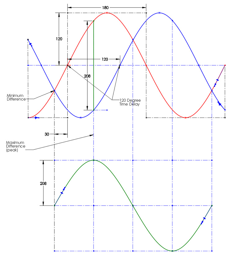
I put together a graph. This was done in SolidWorks, so I don't have a lot of control over making it look pretty. It's only a teaching tool and not intended to be absolutely perfect, so don't nit-pick it. (I know the peak-peak scales are wrong, but its easier to conceptualize.)
In the upper graph, we have the A (red) and B (blue) phase. Their zero-crossings occur 1/3 of a cycle apart. The lower graph represents the difference between them (A-B). The green vertical line represents the point where A-B is a maximum, which is 208 volts.
In the green waveform, its maximum occurs when the difference between A and B is greatest, and it crosses zero when A and B are equal. Its zero crossing occurs 30 degrees before A's zero crossing. However, notice that the lower graph has a new coordinate system that starts when the green line crosses zero. I could have carried the time coordinate system from the upper graph, and that would show the 30 degree time shift in the new graph, but time is relative, and we can set the starting point to what ever is convenient.
The first thing I noticed is that maybe some people are getting hung up on the term "phase shift" or "phase angle". In this particular situation, it might be better to realize that a "phase shift" is simply a "time delay". We call it an angle because we sometimes use phasor diagrams to solve problems, but it is really nothing more than a shift in time. That shift in time is 1/3 of a cycle. Since 1 cycle is 1/60th of a second (at 60 hertz), then 1/3 of that is 1/180th of a second (0.005 sec).
What that means is that when one of our sine waves crosses zero, the next sine wave won't cross zero for another 0.005 seconds. It's been delayed from the first sine wave.
The next thing to realize is that each of the phases in the system is just a single voltage reference. You need two reference points to record a voltage, and our voltmeter is reading just the difference between those points.
Consider two people walking down a 2-lane road with a tape measure stretched between them. They are both told to walk the same speed, so they are always even with each other. They are also told that they have to switch lanes every 10 seconds, but not at the same time. The second person has to wait 3 seconds from the first before he can cross the line, but still 10 seconds apart from his previous crossing.
At any instant in time, you may have both people in the left lane, both in the right lane, or one in each lane. The tape measure stretched between them is going to be constantly changing as they get closer and farther apart. You would think that they would be farthest apart when one of them is at the shoulder, but the second person is already heading toward the center line, so he is closing their distance. They are also not closest together when either one of them crosses the center line because the other one is somewhere in the middle of the other lane.
The tape measure stretched between the two people is analogous to the voltage between phases. It is constantly changing, but its minimums and maximums do not coincide with the minimums and maximums of the two phase voltages (or people's position).
I put together a graph. This was done in SolidWorks, so I don't have a lot of control over making it look pretty. It's only a teaching tool and not intended to be absolutely perfect, so don't nit-pick it. (I know the peak-peak scales are wrong, but its easier to conceptualize.)
In the upper graph, we have the A (red) and B (blue) phase. Their zero-crossings occur 1/3 of a cycle apart. The lower graph represents the difference between them (A-B). The green vertical line represents the point where A-B is a maximum, which is 208 volts.
In the green waveform, its maximum occurs when the difference between A and B is greatest, and it crosses zero when A and B are equal. Its zero crossing occurs 30 degrees before A's zero crossing. However, notice that the lower graph has a new coordinate system that starts when the green line crosses zero. I could have carried the time coordinate system from the upper graph, and that would show the 30 degree time shift in the new graph, but time is relative, and we can set the starting point to what ever is convenient.
