
jeffrey3001
Member
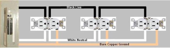
I have Basic Electrical Theory 3rd edition by Mike Holt. In the parallel series examples, it shows a conduit with going to 3 boxes, with receptacles in each box pigtailed off each other as an example of a parallel circuit. It can be found on page 136 if anyone has this. This is an easy concept to grasp as I do it all the time, and instead of a diagram it shows a picture of outlets being pigtailed. Well, on the series circuits all there is diagram , and as I'm not too familar with motor control having a hard time relating. Can anyone show me or explain how you would actually wire 3 different outlets in series? Thanks.
")