You are using an out of date browser. It may not display this or other websites correctly.
You should upgrade or use an alternative browser.
You should upgrade or use an alternative browser.
480 Volt Feeder
- Thread starter eesonny
- Start date
- Status
- Not open for further replies.
- Location
- Massachusetts
I am installing a 480 volt feeder that requires 4-600 MCM per phase. At the top of our MCC if I route through a aluminum plate can I route all A phase through the same hole or do I need to route A/B/C through the same penetration hole?
No, you can only do that underground with PVC or with single conductor MI.
I am installing a 480 volt feeder that requires 4-600 MCM per phase. At the top of our MCC if I route through a aluminum plate can I route all A phase through the same hole or do I need to route A/B/C through the same penetration hole?
You are correct. It is imperative that you route all three phases through the same hole. If you don't the single phase will create a hysteresous magnetic field to occur in the metal around that phase. This will cause a transformer action in the metal which results in a current flow. Because the metal is a very poor conductor it will get hotter than a pistol when current flows through that phase. The more current, the more heat. By routing all 3 phases through the same opening the resultant magnetic field is cancel led out to zero. The only way that you can route a single phase though a single opening is if the material which surrounds the conductor is non magnetic. Often a rectangular opening is cut and a piece of glasstic is fastened in its place and the openings are made in the glasstic.
- Location
- Illinois
- Occupation
- retired electrician
Why can't I use the provisions of 300.3(B)(3) for that application?No, you can only do that underground with PVC or with single conductor MI.
- Location
- Placerville, CA, USA
- Occupation
- Retired PV System Designer
You are correct. It is imperative that you route all three phases through the same hole. If you don't the single phase will create a hysteresous magnetic field to occur in the metal around that phase. This will cause a transformer action in the metal which results in a current flow. Because the metal is a very poor conductor it will get hotter than a pistol when current flows through that phase. The more current, the more heat. By routing all 3 phases through the same opening the resultant magnetic field is cancel led out to zero. The only way that you can route a single phase though a single opening is if the material which surrounds the conductor is non magnetic. Often a rectangular opening is cut and a piece of glasstic is fastened in its place and the openings are made in the glasstic.
The OP stated aluminum. That is not ferromagnetic, but would still conduct eddy currents given the chance.
")
Hysteresis heating is the result of the behavior of a ferromagnetic material in a varying magnetic field and is not an issue here.
But even if a non-conductive material is used or a slot is cut, there is still a question of how the paralleled phase feeders got to the outside of the panel and how they will be secured in the opening if they are not in a raceway.
- Location
- Massachusetts
Why can't I use the provisions of 300.3(B)(3) for that application?
You will need to ask the CMP that question.
I expect for the same reason we can't parallel less than 1/0 even though nothing really prohibits it.
masterinbama
Senior Member
- Location
- Huntsville Alabama
I thought you could use non ferrous glands to terminate from cable tray to switch gear as long as you went through a non ferrous panel.
The OP stated aluminum. That is not ferromagnetic, but would still conduct eddy currents given the chance.
Hysteresis heating is the result of the behavior of a ferromagnetic material in a varying magnetic field and is not an issue here.
,But even if a non-conductive material is used or a slot is cut, there is still a question of how the paralleled phase feeders got to the outside of the panel and how they will be secured in the opening if they are not in a raceway.
I believe that I said that he was correct and gave an explanation as to why he should do it as he described. Also, I indicated what problems occur should he do otherwise. In addition it is not unusual for rabbit trails to occur that are far from the issue of the OP.
I sold some large dry type pad mounted transformers to a well know University out east and my shop technicians very neatly brought the secondary conductors in to the secondary ATC by cutting a hole for each phase, installing a grommet in each and the neatly run each individual phase them each. Unbelievable. And it was not caught by the plant manager nor in final test and inspection.
I have a few other stories that defy all fact reason and logic.
.
- Location
- Placerville, CA, USA
- Occupation
- Retired PV System Designer
I don't doubt it.I have a few other stories that defy all fact reason and logic.
But I was motivated by the fact that although you identified the right behavior, you gave a wrong reason for it. That is sufficient in my view to make it wrong advice.
In a forum like this, I hope that giving the correct reasons is at least as important as giving the right answer.
In fact, a good teacher will often give only the correct reason (e.g. code section) and let the OP figure out what conclusion to draw from it.
OPs are encouraged to come back and test that conclusion, of course.
Ok thanks for all the responses. But I just want to make certain you guys understand my question. You mentioned to route all 3 phases through the same penetration. I asked if I could route 4-"A" phases through one penetration and the same for "B" and "C" not A/B/C through one penetration. The reason for routing in such a manner is because of the CT's mounted on the MCC main bus. The distance from the top of the MCC to the CT's and bus connection is very tight which will not allow me to route A/B/C phases through a penetration and connect to each phase.
- Location
- Massachusetts
I am still lost, can you tell us how the conductors are getting to the MCC?
eHunter
Senior Member
- Location
- North Texas & Georgia
I am still lost, can you tell us how the conductors are getting to the MCC?
The OP stated in post #1 that the conductors will route through an aluminum (non-ferrous) plate on the the top of the MCC. Non-ferrous materials are not highly susceptible to induced current heating.
The conductors would need to be phase grouped as complete individual sets of ABCN/G in any given raceway, which could be a problem for the OP.
Even if these are say single conductors installed in cable tray, I can't see why you'd cut 3 or 4 holes. One hole (or slot) would suffice for all 12 plus any EGC's. Besides that, the conductors should be arranged in A/B/C sets in the tray anyway. He'd have to criss-cross them to get each phase in a separate hole.I am still lost, can you tell us how the conductors are getting to the MCC?
- Location
- Massachusetts
The OP stated in post #1 that the conductors will route through an aluminum (non-ferrous) plate on the the top of the MCC.
Yes I know, but how are they getting to that point, RMC, PVC, free air?
- Location
- Massachusetts
Even if these are say single conductors installed in cable tray, I can't see why you'd cut 3 or 4 holes. One hole (or slot) would suffice for all 12 plus any EGC's. Besides that, the conductors should be arranged in A/B/C sets in the tray anyway. He'd have to criss-cross them to get each phase in a separate hole.
Exactly why I am asking for clarification, maybe there is a logical reason we are not seeing.
- Location
- Placerville, CA, USA
- Occupation
- Retired PV System Designer
+1The OP stated in post #1 that the conductors will route through an aluminum (non-ferrous) plate on the the top of the MCC. Non-ferrous materials are not highly susceptible to induced current heating.
The conductors would need to be phase grouped as complete individual sets of ABCN/G in any given raceway, which could be a problem for the OP.
From 300.20:
Informational Note: Because aluminum is not a magnetic metal, there will be no heating due to hysteresis; however, induced currents will be present. They will not be of sufficient magnitude to require grouping of conductors or special treatment in passing conductors through aluminum wall sections.
Running through aluminum raceway in a single phase group may cause much larger induced currents and create a problem. Since any induced currents are parallel to the wires, they are not significant in a metal plate perpendicular to the wires.
480 volt feeder
480 volt feeder
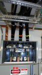
The feeder conductors are 600 mcm 4 per phase routed from a 480 volt switchgear via a cable tray. The switchgear and MCC are in the same building. The connections for the feeder cables at the MCC are located at the top of the MCC in a top hat enclosure provided by the MCC manufacturer. Take a look at the attached picture. My question is are we okay with routing of cable as shown? Thanks again.....
480 volt feeder
The feeder conductors are 600 mcm 4 per phase routed from a 480 volt switchgear via a cable tray. The switchgear and MCC are in the same building. The connections for the feeder cables at the MCC are located at the top of the MCC in a top hat enclosure provided by the MCC manufacturer. Take a look at the attached picture. My question is are we okay with routing of cable as shown? Thanks again.....
Attachments
- Location
- Illinois
- Occupation
- retired electrician
You are not ok if the enclosure or the cable supports are made from ferrous materials.
eHunter
Senior Member
- Location
- North Texas & Georgia
The feeder conductors are 600 mcm 4 per phase routed from a 480 volt switchgear via a cable tray. The switchgear and MCC are in the same building. The connections for the feeder cables at the MCC are located at the top of the MCC in a top hat enclosure provided by the MCC manufacturer. Take a look at the attached picture. My question is are we okay with routing of cable as shown? Thanks again.....
IF the enclosure is aluminum or at least the top plate is aluminum I believe you are ok.
What are the fittings, locknuts and bushings materials?
Plastic is ok.
Iron, steel or any material a magnet will stick to and you are asking for trouble.
Just curious, why does the "B" phase have additional busbar material?
Last edited:
- Location
- San Francisco Bay Area, CA, USA
- Occupation
- Electrical Engineer
...
Just curious, why does the "B" phase have additional busbar material?
Those are shims to make the conductors end up evenly spaced. To be able to bolt the Ell bracket on the vertical bus risers, you end up with an offset in the lug Landing pads. If you just bolt your lugs to it, you end up with the B phase lugs too close to A phase lugs (or C phase as the case may be) and no room for the CT.
- Status
- Not open for further replies.