i was told by 2 masters that this is ok and im still not convinced
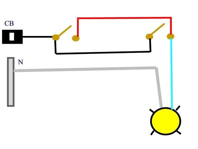
there is a bath fan being controlled by 2 timers 1 in a closet(24hr) and 1 in the bath( 60 min) both are being fed by the same branch circut, however when 1 is on and the other is off there is 120v on the load side of the other and vice versa. this just seems really wrong. any code ref would be greatly welcomed
there is a bath fan being controlled by 2 timers 1 in a closet(24hr) and 1 in the bath( 60 min) both are being fed by the same branch circut, however when 1 is on and the other is off there is 120v on the load side of the other and vice versa. this just seems really wrong. any code ref would be greatly welcomed