I think I have this worked out, but wanted to pass it by someone more knowledgeable to make sure I'm NOT doing anything DUMB!
I have a normally closed 120v relay I need to test live.
It appears to Ohm OK (don't have data sheet) but something is not right.
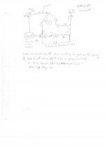
Pin1 to Pin2 (common) = Contacts and supplied by L1
Pin2 (common) to Pin5 = Coil is supplied by L2
==============================
To test the contacts (light bulbs should light, using two in series for safety):
L1 > Light Bulb > Light Bulb > Pin2 (common) > Relay Contacts NC > Pin1 > L1
To test Coil is Working (light bulbs should go out) as Coils should open contacts
CONCERN LIES HERE BECAUSE OF L1 and L2
L2 > Pin5 > Relay Coil > Switch (contacts should Open) > Pin2(common) >Light Bulb > Light Bulb > L1
============
Questions General
============
1. My concern is will the activation of the coil by L2 occur fast enough so that only 120 volts
will appear at Pin2 (common), --OR- because L1 and L2 are out of phase it is Not a concern?
2) Does the above look reasonable?
Thanks
I have a normally closed 120v relay I need to test live.
It appears to Ohm OK (don't have data sheet) but something is not right.
Pin1 to Pin2 (common) = Contacts and supplied by L1
Pin2 (common) to Pin5 = Coil is supplied by L2
==============================
To test the contacts (light bulbs should light, using two in series for safety):
L1 > Light Bulb > Light Bulb > Pin2 (common) > Relay Contacts NC > Pin1 > L1
To test Coil is Working (light bulbs should go out) as Coils should open contacts
CONCERN LIES HERE BECAUSE OF L1 and L2
L2 > Pin5 > Relay Coil > Switch (contacts should Open) > Pin2(common) >Light Bulb > Light Bulb > L1
============
Questions General
============
1. My concern is will the activation of the coil by L2 occur fast enough so that only 120 volts
will appear at Pin2 (common), --OR- because L1 and L2 are out of phase it is Not a concern?
2) Does the above look reasonable?
Thanks