300.3

Status
Not open for further replies.

Cavie

Senior Member
Location
SW Florida
I agree all the grounded conductors should be terminated on this buss without the bonding screw. EGC's should have been bonded to the enclosure. What can I do? This was installed by the company I work for and was told by the owner, "just get this through plan review".


And your answer should be........"With all due respect sir"........yadayadayada, cause your gonna take the fall for it with the PE if he knows what he's doing.
 

Twoskinsoneman

Senior Member
Location
West Virginia, USA NEC: 2020
Occupation
Facility Senior Electrician
Then the green bonding screw should not be installed as the transfer switch does not switch the grounded conductor.

I am lost now. The grounded conductor from the pin and sleeve goes straight through the enclosure. The conductors connected to the block are green so clearly grounds right? So wouldn't you want them connected to the enclosure... It isn't like your are bonding the neutral...
 

Cavie

Senior Member
Location
SW Florida
I agree all the grounded conductors should be terminated on this buss without the bonding screw. EGC's should have been bonded to the enclosure. What can I do? This was installed by the company I work for and was told by the owner, "just get this through plan review".

Can you get it though plan review AND the inspector?? I overrode plans review more than once.
 

RUWired

Senior Member
Location
Pa.
Then the green bonding screw should not be installed as the transfer switch does not switch the grounded conductor.
chris said:
I agree all the grounded conductors should be terminated on this buss without the bonding screw. EGC's should have been bonded to the enclosure. What can I do? This was installed by the company I work for and was told by the owner, "just get this through plan review".

What article requires the feeder grounded conductor to be terminated in an enclosure?
 
trim your bush

trim your bush

Your green screw "bonding Jumper" I'm sure is probably Ok. It was probably sent with the transfer switch to bond the bus bar to the can. perhaps to be used as a bonding jumper on a seperately derived sys, or a service. The extra studs, and lugs could possibly be for your grounding electrode conductor, or for other bonding reasons. I'm sure that since the wires required in art 250.66 are larger than the wires required in art 250.122 the bonding jumper sent with the equipment would be ok for your equipment ground. I'm being lazy by not looking into the grounded conductor not being ran with the phase conductors any further, so I will take a hip shot . I will assume that the line and load being ran in the same conduit would be ok being that the emf from the conductors will still cancel each other out, and cause no heating on your metal raceways.

You should take a look at your bush. In the picture there is a bush in front of your electrical equipment. I would get those plants out of my working space.
Johnnyelectric001
 

RUWired

Senior Member
Location
Pa.
I have an existing MTS that I believe is in violation of 300.3. Normal power comes in with just 2 4/0's. I believe there is an exception for switches that allows this install without the grounded conductor run with them. I cant find this exception in 300 or 400. Where is it???

Chris 300.3(B) says where the grounded conductor is used it needs to be in the same raceway. The way the switch is wired, your not using it. If you carried the neutral into the switch and then onto, you would be using it and then it would be required to be in the same raceway.
chris said:
The load leaves in the same nipple but with the 4/0's and the #3 grounded conductor from the generator inlet device goes to the MDP. This I believe is in violation.

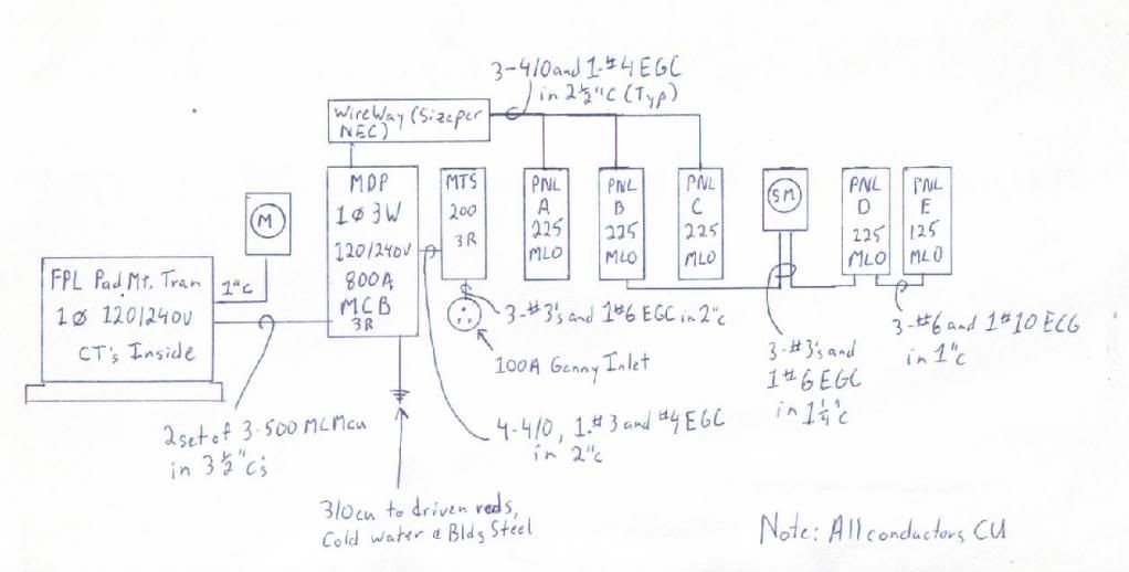
Also, I need to submit a riser diagram to the building dept on Monday. How would you list the conductors in that conduit??? 4-4/0's, 1-#3, and 1-#4EGC in 2" conduit???
You can list it the way it is but you have the violation of 352.22 to contend with unless the raceway is not over 24". I also see 225.31,32,36,37 as violations along with 200.6.
 

chris kennedy

Senior Member
Location
Miami Fla.
Occupation
60 yr old tool twisting electrician
Chris 300.3(B) says where the grounded conductor is used it needs to be in the same raceway. The way the switch is wired, your not using it. If you carried the neutral into the switch and then onto, you would be using it and then it would be required to be in the same raceway.

I understand this Rick, my problem is the #3 grounded conductor from the generator inlet running through the MTS into the MDP.


You can list it the way it is but you have the violation of 352.22 to contend with unless the raceway is not over 24". I also see 225.31,32,36,37 as violations along with 200.6.
It is a nipple. All the 225 sections you list are from part II, "More Than One Building or Other Structure". Thats N/A.

Can we see your sketch ?

This is what I have.

LibertyBellriser.jpg
 

don_resqcapt19

Moderator
Staff member
Location
Illinois
Occupation
retired electrician
I am lost now. The grounded conductor from the pin and sleeve goes straight through the enclosure. The conductors connected to the block are green so clearly grounds right? So wouldn't you want them connected to the enclosure... It isn't like your are bonding the neutral...
You are correct, I posted that with out referring back to the pic.
 

chris kennedy

Senior Member
Location
Miami Fla.
Occupation
60 yr old tool twisting electrician
To the tap rules allow all of those MLO panels, especially the sub-fed ones?

There are no taps. Each 225A breaker in the MDP has 3-4/0's and EGC that pass through the gutter without taps or splices. Panels D and E are fed from their respective panels via compliant breakers and feeders.

Each breaker has 2-4/0's and the corresponding grounded and equipment grounding conductor passing through the gutter.
 
Last edited:

LarryFine

Master Electrician Electric Contractor Richmond VA
Location
Henrico County, VA
Occupation
Electrical Contractor
There are no taps. Each 225A breaker in the MDP has 3-4/0's and EGC that pass through the gutter without taps or splices. Panels D and E are fed from their respective panels via compliant breakers and feeders.

Each breaker has 2-4/0's and the corresponding grounded and equipment grounding conductor passing through the gutter.
Aha. The drawing gives the impression there's only an 800a MCB.
 

hurk27

Senior Member
Panel A which is the office's of this truck repair/warehouse facility.

Errrr
A 200 amp transfer switch switching a 225 amp load?
or do you have a 200 amp breaker in the MDP for this panel?

As far as 300.3 goes, we wouldn't be able to run dead end switches if we had to run the neutrals in a case like this, Johnnieelectric touched on this in post 27.
 
Last edited:

al hildenbrand

Senior Member
Location
Minnesota
Occupation
Electrical Contractor, Electrical Consultant, Electrical Engineer
As far as 300.3 goes, we wouldn't be able to run dead end switches if we had to run the neutrals in a case like this, Johnnieelectric touched on this in post 27.
I don't think there's any way to avoid bringing the 225 A feeder neutral from the MDP to the transfer switch, and then have the feeder neutral continue from there on to the main lugs of Panel A.

If Panel A were only 240 V loads, that is, no unbalance current on the neutral, then one could argue the comparison with a dead end switch, however, Panel A is for the offices of this trucking company. The load is inherently unbalanced.

Without the feeder neutral going to, and going on from, the transfer switch, there will be a net magnetic field at the transfer switch, and in the raceway leading into it from the MDP, whenever the system is on Utility power.
 

hurk27

Senior Member
I don't think there's any way to avoid bringing the 225 A feeder neutral from the MDP to the transfer switch, and then have the feeder neutral continue from there on to the main lugs of Panel A.

If Panel A were only 240 V loads, that is, no unbalance current on the neutral, then one could argue the comparison with a dead end switch, however, Panel A is for the offices of this trucking company. The load is inherently unbalanced.

Without the feeder neutral going to, and going on from, the transfer switch, there will be a net magnetic field at the transfer switch, and in the raceway leading into it from the MDP, whenever the system is on Utility power.


A'hhhh, I wasn't thinking about that, thank's
I think me brain cells needs a little kick start some times:D
and if this was from a 3-phase Y service (which its not) the more reason for the neutral.
 
Status
Not open for further replies.
Top