current returning to a different source

Status
Not open for further replies.

Smart $

Esteemed Member
Location
Ohio
rattus said:
Smart,

Regardless of phraseology, nit-picking that is, you agree that capacitive current returns either to another line and/or to earth.
No.

I say it returns to the same line.

Edit to add: From a capacitve premise, upon approach to the line the helicopter is adding a minute plate to one side of a multiplate capacitor in an otherwise very large RCL circuit. Because it is so small in the overall circuit and because it is not connected to anything, it neither increases nor decreases current of the existing circuit by any appreciable amount. Upon arcing it becomes part of one plate and again neither increase nor decreases the current of the RCL circuit.
 
Last edited:

rattus

Senior Member
Nonsense!

Nonsense!

Smart $ said:
No.

I say it returns to the same line.

You will have to justify that statement. That is not the way I heard it.

You are saying that I wasted all that time in AC Circuits, Physics, Calculus, DE, AC Machinery & Lab, etc., etc., etc. I want my money and my youth back!
 

Smart $

Esteemed Member
Location
Ohio
rattus said:
You will have to justify that statement. That is not the way I heard it.
See my edit... I'd already anticipated flack on my initial statement!

You are saying that I wasted all that time in AC Circuits, Physics, Calculus, DE, AC Machinery & Lab, etc., etc., etc. I want my money and my youth back!
No, I'm not saying that. Besides, whether you wasted your time or not is something only you can determine.

Regarding your guise of never being wrong, I'm sure it has encouraged you to seek and discover many truths. Your knowledge is most commendable.
 

zog

Senior Member
Location
Charlotte, NC
crossman said:
I would like to rephrase my previous question concerning an experiment with a "high-pot" tester.

See diagram below. We have a conductive body suspended in the air and perfectly insulated. Both ammeters properly calibrated. Hi-pot enclosure/chassis suspended and perfectly insulated from earth and from the grounded test lead and from the supply. No ground connections to high voltage secondary except through the ammeter. Hi-pot lead is arcing to the conductive body.

Would the meters read substantially the same? Or substantially different?

Rattus?
Rick?
Jghrist?
Smart $?
Zog?
Winnie?
quogueelectric?

test4.jpg

I dont have an exact answer for you but they will not be the same. I tried this with a 5kV megger by comparing leakage current (Calculated) gaurded and ungaurded. Gaurded values were about 40% less the ungaurded.

I would rather do this wih my 100kV hipot (Or even 50kV) but they dont have a gaurd circuit and I dont have any ammeters I want to fry.
 

rattus

Senior Member
Smart $ said:
See my edit... I'd already anticipated flack on my initial statement!

The relative value of the caps is unimportant. Before the arc is struck, we have two caps in series.

Current will flow in these two caps.

After the arc is shorted, we have a lumped cap on the line. Current will flow in this cap!.

In neither case does the current return to the same line.
 
Last edited:

Smart $

Esteemed Member
Location
Ohio
rattus said:
The relative value of the caps is unimportant. Before the arc is struck, we have two caps in series.

Current will flow in these two caps.

After the arc is shorted, we have a lumped cap on the line. Current will flow in this cap!.

In neither case does the current return to the same line.
Anyone using a capacitance premise to explain the arcing cannot simply limit the components to capacitors. The system generating the charges also has resistance (transmission lines mainly) and inductance (windings in all connected transformers, source and loads). If you are going to include capacitance between lines and lines to ground, you must also include capacitance to air. And in all of that, not only are the relative values of the caps important, so are all other values. What this amounts to is: if one is going to describe the effect as a circuit, then all components of the circuit must be entertained.

By maintaining your capacitor premise you have failed to account for all contributing variables.

I prefer to take the simpler route and explain the arcing as simple static discharge. The main difference between this type of discharge and the type we commonly see and/or experience in nature is that the electrostatic field has [a continuously] alternating polarity [and consistant magnitude] ... therefore the arc can be maintained under the conditions by which it occurs.

[edited text]
 
Last edited:

rattus

Senior Member
Smart,

We have capacitors. We have voltages impressed across those capacitors. Therefore we have current in those capacitors. Can you deny that??

The phase voltages are stiff sources capable of providing hundreds, maybe thousands of amperes. No need to consider any other parameters.

You are not making a cogent argument. Let me repeat a quote which I posted pages and pages ago:

"A steady current can exist only in a closed circuit.........."

(Applies to AC as well as DC)

[Sears, F. W. "Electricity & Magnetism", Addison-Wesley, 1954]

F. W. Sears was a Professor of Physics at MIT. What you are saying violates this well-known, proven principle.

Case closed!
 

jghrist

Senior Member
zog said:
I dont have an exact answer for you but they will not be the same. I tried this with a 5kV megger by comparing leakage current (Calculated) gaurded and ungaurded. Gaurded values were about 40% less the ungaurded.

I would rather do this wih my 100kV hipot (Or even 50kV) but they dont have a gaurd circuit and I dont have any ammeters I want to fry.
If the chunk of metal is indeed isolated from ground (no resistive leakage), then where does the current go to from a dc megger, after an initial transient charging current? :confused:

Where did you connect the guard circuit?

Is the 100 kV hipot a dc hipot or an ac hipot?
 

crossman

Senior Member
Location
Southeast Texas
Gentlemen:

In my understanding, it has been speculated in this thread that current can flow from one terminal of an AC source to an insulated conductive body and that this does not rely on capacitance, which is defined as two conductive bodies seperated by an insulator.

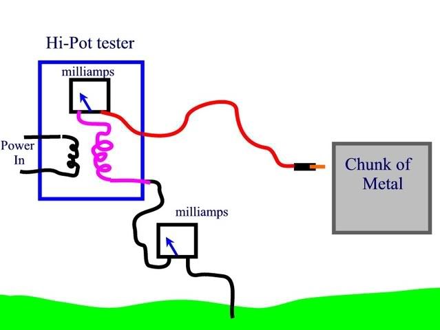
An experiment was posted in which an AC high-pot tester had one lead attached to a suspended conductive body and an ammeter did indeed indicate a current flow back and forth to the conductive body. It was speculated that this current flow has nothing to do with capacitance. The term "electron reservoir" was used in conjunction with the conductive body.

Now, during this experiment, it was said that the other terminal of the high-pot tester was connected to the earth.

If I am viewing this experiment from the moon, then it is obvious to me that the earth is nothing other than a huge conductive body. In actuality, it is no different than the other conductive body, only much larger. There is nothing special about the earth in this experiment. And it (the earth) is attached to one terminal of the high voltage source. Whatever laws of physics are acting on the small conductive body and causing current to flow to it must also be acting on the other conductive body too (the earth).

This leads to the following:

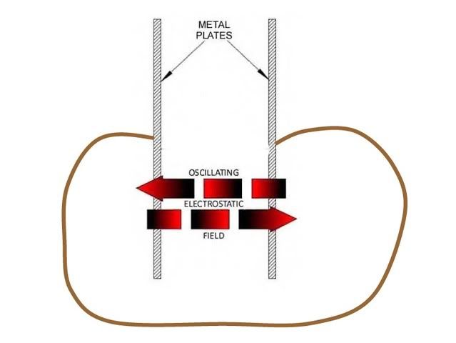
1) The lead going to the conductive body is always of opposite polarity compared to the lead connected to the earth. It follows that the conductive body will always be of opposite polarity to the earth. Anytime that the conductive body is negative, the earth will be positive, as compared to each other. And anytime the conductive body is positive, the earth will be negative compared to each other. Now, the very definition of a capacitor is two oppositely charged conductive bodies seperated by an insulator. The conductive body and the earth form a capacitor.

2) If we remove the small conductive body from the experiment, we still have the earth connected to one side of a high voltage source and this source is constantly changing polarity in respect to the other terminal of the source. It follows that the earth is also constantly changing polarity in respect to the other side of the source. If the speculated theory is correct (and using the exact same mechanism which caused current to flow to the small conductive body), then a current must flow between the earth and the terminal of the high-pot tester. After all, what is the difference between one terminal of the source connected to the small body , or the other terminal of the source connected to earth? (It isn't because that terminal is grounded. The ground connection is simply a connection to a large conductive body and all the laws of physics still apply. The earth is in fact, simply a conducting body and no different than the other conductive body except for size.)

3) I suspect that the metal chassis/enclosure of the high-voltage tester is connected to one side of the high voltage source. If this is true, and assuming the speculated mechanism is true, then current must be flowing continuously between the chassis/enclosure and the source terminal that it is connected to. This would be regardless of whether the small conductive body was connected to it or not. And the speculated theory says this current is not due to capacitance.

4) If the specualtion is true, the high-pot probe itself is actually a conductive body attached to a source terminal. So current should be flowing back and forth from the probe to the source terminal it is connected to. The high-pot meter should read something even when nothing is in the vicinity of the lead. It would probably be said that since the probe is relatively small, it doesn't take much current to equalize it to the changing polarity of the terminal. The current may be so small, it can't be measured.

5) Let us consider the speculation to be true that it only takes one wire to a conductive body to cause current to flow and "equalize" the voltage on the terminal and the conductive body, and that this does not require capacitance. An extremely small conductive body would not require very much current to equalize it to the terminal it is connected to, as in #4. A slightly larger body would require somewhat more equalizing current. It follows that a larger conductive body would require even more current to "equalize" the body. Now, the current required to "equalize" the earth to the terminal it is connected to would be tremendously huge, possibly thousands of amps.


If there is a hang-up with "but you are wrong because one of the high-pot leads is grounded and ground is the reference, and therefore doesn't change", well you are wrong. It is just as perfectly valid to claim the small conductive body is going to be the reference as it is to claim the earth is going to be the reference. The same laws of physics and the same current flows will occur regardless of what point I choose as the reference.

For example, take the service at your house. We can use the neutral point as the reference for all voltages and current flows in the system. But we could just as easily claim that one of the phase terminals is to be the reference, and the physics and math would still be the same. Sure, some polarites would change, some of the data would be different, but any equations and laws would still compute to the same answers for any variable in the system.

Another point to consider - take a delta 3-phase 3-wire system. According to the speculated theory, any conductive body attached to a phase wire is going to experience a continuous equalizing current flow that has nothing to do with capacitance. To keep this body at the same potential as the phase wire, there must be a constant current flow.

If we connect a conductive body to only "C" phase, the specualtion is that non-capacitive current should flow. If we connect a larger "electron reservoir" to "C" phase, even more current would flow. It follows that if we connect "C" phase to a conductive body larger than the earth, then a very large current should flow.

If we connect "C" phase to the earth as in a grounded phase delta, then "C" phase must keep the earth at the same potential as the phase. To do this, a current must flow between the phase and the earth.... most likely a huge current flow. And it isn't capacitive current according to the speculation.

Now, again, to defend the speculated theory, a person may say that the earth is the reference and doesn't change polarity. But that is only because we are standing on earth. If I was standing on a conductive body connected to "A" phase, then I would say THAT conductive body is the reference, not the earth. My physics and calculations done from my perspective would derive the exact same current flows as someone else from a different reference point.

There is nothing special about the earth that makes it different from any other conductive body we connect to a phase wire. It just so happens it is convention to accept the earth as reference. It doesn't mean we have to. We can choose anything we want to for the reference. As long as we are consistent, the calculations will all derive the exact same results.

It appears that the specualted theory leads to some absurdities. I therefore believe the specualted theory is false. Capacitance is the mechanism behind the current flows.

For anyone who has bothered to read this far: There are some more points to be made based on the movement of electrons to the conductive body and where these charges are coming from. Whenever electrons move, there will be positive charges left behind. These positive charges in turn attract more electrons. And so on and so on, all the way back to the source, then through the source, and in the case of the high-pot, then to the earth, and then through the earth from the point where the negative charge in the conductive body is repelling those very electrons in the earth.

Hi-pot experiemnt: Capacitance between the conductive body and earth and any other grounded items in the area.

Helicopter: Capacitance between individual phases, the earth, and the helicopter.

Thanks for reading!:smile:
 

Smart $

Esteemed Member
Location
Ohio
rattus said:
Smart,

We have capacitors. We have voltages impressed across those capacitors. Therefore we have current in those capacitors. Can you deny that??
I know we have mass. Capacitance of mass is an inherent property.

Other than that, the bodies of mass in this discussion do not meet my definition of a capacitor. For the sake of discussion they can be likened to capacitors... but I'll not call them capacitors.

The phase voltages are stiff sources capable of providing hundreds, maybe thousands of amperes. No need to consider any other parameters.
Let me see if I'm getting this right...

For your argument, parameters other than the ones you mention can be ignored. Correct? (rendundant)

On the other hand, in my earlier suppositions, I said the capacitance to ground can be ignored. You, essentially, said I could not.

So it appears to me your basis for argumentation is biased.

You are not making a cogent argument.
An argument is never cogent to a closed mind.

Let me repeat a quote which I posted pages and pages ago:

"A steady current can exist only in a closed circuit.........."

(Applies to AC as well as DC)

[Sears, F. W. "Electricity & Magnetism", Addison-Wesley, 1954]

F. W. Sears was a Professor of Physics at MIT. What you are saying violates this well-known, proven principle.
Circuit, by its very definition, requires it to be closed path.

That's analogous to saying, "A winner of a multilap race can only exist if the course is a closed path."

Here's a question for you. Considering the depiction that follows, will current flow through the single conductor?

View attachment 1277

Case closed!
So does this mean you'll not contest anything others and myself post hereafter?
 

crossman

Senior Member
Location
Southeast Texas
Smart, the single wire in your diagram is actually completeing the path from one side of a source to the other. The oscillating field between the plates, without a doubt, forms a voltage source. There is absolutely a complete circuit from one side of the source to the other. Your drawing would be akin (other than AC vs DC) to taking a straight piece of wire and a car battery with the negative and positive posts on the top of the battery, then connecting those posts together with the straight wire and saying it wasn't a complete circuit.

Draw it a little different, it is exaclty equivalent electrically, only now, not only is it a complete circuit, it also looks like a complete circuit.

smart.jpg
 

Smart $

Esteemed Member
Location
Ohio
crossman said:
Smart, the single wire in your diagram is actually completeing the path from one side of a source to the other. The oscillating field between the plates, without a doubt, forms a voltage source. There is absolutely a complete circuit from one side of the source to the other. Your drawing would be akin (other than AC vs DC) to taking a straight piece of wire and a car battery with the negative and positive posts on the top of the battery, then connecting those posts together with the straight wire and saying it wasn't a complete circuit.

Draw it a little different, it is exaclty equivalent electrically, only now, not only is it a complete circuit, it also looks like a complete circuit.
I'm not going to argue that you can't use your premise. All Rick and I have been saying all along is that it is not the only premise, and our premise is, well, technically much more simple. You subscribe to the principle there must be a complete closed circuit for [steady] current to exist. Rattus says it applies to both AC and DC. However, for AC to exist, there has to be an instances in time were no current is flowing. Therefore the term "steady current" is an oxymoron regarding AC. Somebody has made an explanation of certain events in certain terms and those who choose to adhere to that explanation seem to be convinced that all events must fit the explanation, rather than revising the explanation to more accurately fit all events. The same thing happened with the direction awhich current flows. So who's right? The philosophical answer is: The only difference between right and wrong is what we think!

BTW, regarding my recent depiction, the plates are supposed to be entirely within the electrostatic field, rather than the field in between the plates. Makes little difference though.

But I do need to point out that when you take the conductor around the plates, it is not electrically equivalent... the current direction is opposite that of a conductor in between the plates.
 

rattus

Senior Member
Smart,

You must have written your own Physics text because you refer to your interpretation rather than to facts.

There are "closed circuits" and "open circuits". Your nit-picking of my quote is simply your method of side-stepping the obvious.

There can be no field between two shorted plates.

"Case closed" means I have proven my point with one simple quote and do not wish to argue about your home grown interpretations.
 

zog

Senior Member
Location
Charlotte, NC
jghrist said:
Depends on if the chunk of metal is closer to the earth or to the grounded case of the tester. If closer to the earth, then the currents will be about the same. If the chunk of metal is closer to the tester than to any other grounded objects on the ground side of the milliammeter, then the current in the ground lead will be lower.

I considered that possibilty and that might be what happened in my experiment. There is definitly a strong field around this whole set up, i had a tic-tracer and it was going off in every part of the room, so there may be several things happening, parallel paths all over the place.

Same could be said about the helicopter, i think we are trying to over simplfy with these cute little drawings (Some of them are quite good actually), this is a very complex circuit and we dont just have current flowing from point A to B.
 

crossman

Senior Member
Location
Southeast Texas
Smart $ said:
But I do need to point out that when you take the conductor around the plates, it is not electrically equivalent... the current direction is opposite that of a conductor in between the plates.

As far as a completed path is concerned, the current is flowing in the same direction.

1) take a look at the wire at the bottom of the page. The current in this portion of the wire is flowing in the same direction as your wire.

2) the direction of electron current flow will always be from the negative plate to the positive plate of your voltage source, regardless of how the wire is routed.
 

crossman

Senior Member
Location
Southeast Texas
Another conclusion which can be drawn from the speculated theory is that it is commonplace for more electrons to flow out of the negative side of a xfmr secondary than flow into the positive side of the secondary at a given time. This is simply not the case.

Again, take the AC high-pot tester. It is well-known that the secondary leads are changing polarity. It should also be obvious that the electromagnetic field of the xfmr is trying to move electrons from the positive terminal to the negative terminal of the secondary (yes, inside of a voltagesource, electrons flow from the positive terminal to the negative terminal).

In a given quadrant of the sine wave, let us say that electrons are flowing out of the negative terminal to the conductive body. This means that the negative terminal of the xfmr has actually become more positve than it was. And since the electromagentic field is attempting to pull electrons from the positive terminal and push them to the negative terminal, electrons from the positive terminal will certainly move to the negative terminal. This means that the positive terminal has become even more positive. Anything connected to the positive terminal will now give up electrons which will move into the positive terminal. With the high-pot, this is the earth and anything connected to it. And there we again have two oppositely charged bodies seperated by an insualtor and there will be an electrostatic field between them. And the entire reason why current can flow to the conductive body in the first place is capacitance.

If electrons are to leave the negative terminal of a xfmr secondary, electrons must flow into the positive side of that secondary. It is similar to a "chain reaction". I personally believe this to be a law of physics based on "conservation of charge." And contary to beleive, I have given large amounts of thought, research, and study time to this subject.

Electrons simply cannot move around and accumulate on conductive bodies without leaving positive charges in their wake. And those accumulating electrons are intimately tied to the positive charges created by their absence. This intimate tie is the electrostatic field. It is like the "two capacitors with a switch between them" diagram posted previously.

And once again, this is capacitance.
 

crossman

Senior Member
Location
Southeast Texas
Let me elaborate a little more on the actual speculated theory, which on first hand, does have some merit if you think about it from a certain perspective. I will make the attempt.

Again, use the high-pot diagram. In the first quadrant of the sine wave AC voltage, the secondary voltage from terminal to terminal is increasing. Let us say that in this quadrant, the "high-voltage probe" is attached to the negative terminal. Electron current is flowing to the conductive body from the high-voltage probe to "equalize" the body to the negative terminal of the high pot. The conductive body will charge up to a voltage near 100 kV in respect to the grounded terminal of the high-pot.

Now, in the second quadrant, the voltage between the secondary terminals will be decreasing, let's pick a point on the second quadrant where the voltage is 50 kV. Since the conductive body is now at a higher potential than the negative terminal, current will flow backwards against the source. Obviously the voltage on the conductive body is decreasing as it discharges back to the source, but for every instant, its voltage to the grounded terminal is higher than the voltage of the ungrounded terminal as measured to the grounded terminal.

Then in the third quadrant, the polarity swaps and the conductive body will have electrons pulled off it. It charges to a positve voltage in respect to the grounded terminal. It will charge to near 100kV positive in respect to the opposite terminal.

Then in the fourth quadrant, the secondary voltage is again decreasing, pick a poiint where the voltage is 50 kV between the secondary terminals. The positive voltage in the conductive body will "overpower" the voltage of the source and electrons will flow to the conductive body, even though the source would rather them flow in the opposite direction.

Then we start the entire thing over. Looking at this, the curent flow is 90 degrees out of phase with the voltage, and there is nothing wrong with that. So far, the speculated theory looks plausible.

However, it is only looking at one side of the coin. If we are to make any conclusions about the curent flow to and from the conductive body, we need to consider all forces applied to the conductive body. And that is where the electrostatic field comes in.

We cannot simply look at only the ungrounded high-pot terminal, the wire, and theconductive body. If we only consider those items, then it appears that current flow is supported by only those items.

But to be physically rigorous, we must look at the rest of the story. As I mentioned before, anytime that electrons are moving about in sources, wires, and conductive bodies, there are positive charges being created by the absence of the electrons which moved. And these positve charges will have an affect on the all of the items mentioned above. If the earth is attached to one side of the secondary, then it too will play just as large a role in the current flow as the conductive body. It is called an electrostatic field. In fact, the only current flow that can occur to the conductive body is exactly predicted byt the capacitance to which it is connected. You simply cannot ignore what is happening at the other side of the source if you want to understand what is truely happening. Negative bodies, positive earth. Positive bodies, negative earth. It all works together. Capacitance. And this explains the 90 degree phase shift too.

Thank you for taking the time to read this.
 
Last edited:

crossman

Senior Member
Location
Southeast Texas
zog said:
There is definitly a strong field around this whole set up, i had a tic-tracer and it was going off in every part of the room, so there may be several things happening, parallel paths all over the place.

This is good to hear. I would suspect that the "strong field around this whole set up" is due to the electrostatic fields created by the capacitance from the conductive body to the grounded building, the grounded test stand, any grounded bodies in the area, and even the earth itself.
 

Rick Christopherson

Senior Member
crossman said:
Another conclusion which can be drawn from the speculated theory is that it is commonplace for more electrons to flow out of the negative side of a xfmr secondary than flow into the positive side of the secondary at a given time. This is simply not the case.
You are quite correct. Any electrons flowing out of the transformer must be made up for by electrons flowing into the transformer. This is covered by Kirchoff's rule. However, the electrons that enter the transformer are not necessarily (figuratively) the same as those leaving the transformer.

In this particular example, the Earth is acting as an electron Source, and the helicopter is acting as an electron Sink (obviously this reverses with the AC cycle).

I apologize, but I have not read the entirety of your two postings, so I don't know how this may or may not relate to anything else you wrote.
 

Smart $

Esteemed Member
Location
Ohio
crossman said:
As far as a completed path is concerned, the current is flowing in the same direction.

1) take a look at the wire at the bottom of the page. The current in this portion of the wire is flowing in the same direction as your wire.

2) the direction of electron current flow will always be from the negative plate to the positive plate of your voltage source, regardless of how the wire is routed.
I'm getting the impression you are thinking of an e-field more from the electromagnetic point of view.

After so much has been written, I'm beginning to ask myself, what exactly are we trying to explain/answer? So I put forth that very question to you.
 
Status
Not open for further replies.
Top