mwm1752
Senior Member
- Location
- Aspen, Colo
With a 1200 amp service near this bed nighstand area,in our experience 1mg. is never going to be achieved ( no matter what you do-even shielding) unless you turn off all the power.Someone is dreaming in tecnicolour.
Thanks Ron, my confusion come from his analysis of no current on the grounded conductor of the the service. This would indicate that the loads are balanced & not something that is baffling or alarming. a balanced 120/208 system would not have EFL's I presume. I get parallel paths & shared neutrals of different circuits & how that would in fact unbalance the conduit/cable & emit EFL's. The service is also where the electrode system would bond to the grounded conductor and all metal surfaces as required. So the video stresses the net currents which should equal 0 when placing an amprobe around all circuit conductors of a feeder/branch circuit.
Maybe there is an inappropriate N-G bond and the current normally expected on the grounded conductor is on the grounding conductor (or shared) causing imbalance.
I look forward to any pictures you'll get.Even if that was true - the current would take all paths -- he states supply side nuetral which is my service conductors & technically the only path back to the utility --
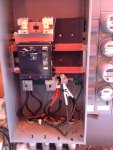
Phase A = 119 Amps, Phase B = 101 Amps, Grounded Conductor = 16 Amps
4 Parallel runs each pipe contains A, B, GC - measured ?Net Current? each run
Pipe 1 = .06 Amps, Pipe 2 = 6.2 Amps, Pipe 3 = 4 amps, Pipe 4 = .09 Amps
Did not have an amp loop long enough to encompass the complete service lateral
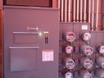
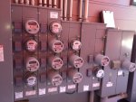
For unknown reasons my readings do not match the report readings, still curious why 2 out of 4 parallel runs show a significant net current reading. Service has an UFER grounding system & water piping CU. The gas service piping has no reading and the transformer is within 50? of the service equipment and has its own GES. The only connection to the GC & GEC is in the Main disconnect.
OK good info.
You will have to divide your net currents into 2 categories: the service (incoming feeds, GECs, main disconnect) and the feeder to the apartments.
I mention individual feeders because there is a very good chance in the very least one or two of those apartments has an improperly done subpanel, ditto with a standing neutral to ground fault on a branch circuit. Every other apartment Ive seen has an improperly done subpanel where the bonding screw want removed or something along those lines. This would cause current to flow on the metal conduits and in turn the chassis of the meter bank creating elevated magnetic fields. Current will also be forced onto EGCs in the subpanel traveling to appliances with metal water lines back to the water bond (which again creates elevated EMF).
For the service I recommend multiple clamps to determine the ratio of net current between the service conductors and the GECs. If the ratio is high, for both, than that would indicate an problem with the service like an open neutral.
In a perfect world I would go in there and trip the main and analyze circuit by circuit and megger, but considering apartments and impossible to go into each one this has to be done entirely via amp clamps and logic.
Can I get accurate reading clamping around the feeder pipe on the load side of the OCPD? or will the metal piping hinder the measurement