GEC requirement for PV Switch 2020 NEC

jot30

Member
Occupation
Electrician/Electrical Inspector
We just adopted the 2020 NEC and I have a question related to the PV switch, requirement of NEC 250.25 Neutral to case bond. As has been discussed in this forum at length before 😊, although, it made sense a utility line side tap would cause the PV switch to be service equipment, it was unclear in the 2017 NEC if the N/G bond was required.

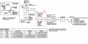
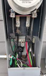
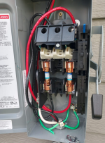
I have a question regarding the PV switch GES/GEC requirements. We (I) never installed solar in my career, but am responsible for inspecting PV systems now. I included a one-line drawing of a common residential system I see in our area. Utility here does not allow the tap in the meter any longer, so what I see now is the line side tap ahead of the main in the MDP. (the pic is a meter line side tap- didn’t have one in the MDP) The typical installation from the PV switch is bonding bushings EGC’s back to the MDP. (see pics) In my area all installations are mostly “pipe and wire” the MDP’s presently are inside the residence and a N/G case bond at the MDP.

My question is since the PV switch outside now gets a N/G case bond per 250.25, are you required to also bond to the water ground and all other available electrodes and if so, how is that typically accomplished to satisfy code requirements. Separate GEC’s to electrodes?

In my area there are typically bonding bushings on the line side nipples – Meter to MDP, (GEC electrodes (rods) N/G bond to meter case – this is a utility requirement) N/G bond MDP – where Water GEC and UFER GEC if present would land. I realize the EGC bonds will now stop at the PV switch.
 

Attachments

  • one-line.png
    one-line.png
    122.7 KB · Views: 36
  • Meter Tap.png
    Meter Tap.png
    714.3 KB · Views: 37
  • Switch.png
    Switch.png
    994.7 KB · Views: 36

jaggedben

Senior Member
Location
Northern California
Occupation
Solar and Energy Storage Installer
See 250.64(D). There are three options. Bascially do it upstream, run separate GECs to the electrodes, or tap off a common GEC to each disconnect.

My first choice, all else being equal, would be to connect the GEC(s) to the neutral in the box where the supply-side tap is done, if that's what the drawing is actually showing.
 

jaggedben

Senior Member
Location
Northern California
Occupation
Solar and Energy Storage Installer
As I look at the photo with the tap, I'm not 100% sure that there isn't a GEC landed on the neutral bar, left side. If so, and that connects (eventually) to all the electrodes, then the grounding is done.

The ground bar they evidently added to the enclosure is odd and unnecessary. But I wouldn't say it has to be removed.
 

jot30

Member
Occupation
Electrician/Electrical Inspector
See 250.64(D). There are three options. Bascially do it upstream, run separate GECs to the electrodes, or tap off a common GEC to each disconnect.

My first choice, all else being equal, would be to connect the GEC(s) to the neutral in the box where the supply-side tap is done, if that's what the drawing is actually showing.

Thanks for the reply ..."connect the GEC(s) to the neutral in the box where the supply-side tap is done"...
I know I provided a picture with the tap in the meter, but utility doesn't allow that anymore, so the line side taps are now in the MDP ahead of the Main Breaker - OCPD. The water GEC and Ufer are already bonded in the MDP for the main service. How do you establish the GEC bond for the PV switch... "tap off a common GEC to each disconnect"... instead of a pierce tap to the line side neutral from the switch do you linstead and the neutral on the already bonded neutral bar in the main service.
 

jot30

Member
Occupation
Electrician/Electrical Inspector
As I look at the photo with the tap, I'm not 100% sure that there isn't a GEC landed on the neutral bar, left side. If so, and that connects (eventually) to all the electrodes, then the grounding is done.

The ground bar they evidently added to the enclosure is odd and unnecessary. But I wouldn't say it has to be removed.
The green on the small lug is the EGC/jumper from the bonding bushing coming from the Switch. The other bonded green #6 - going behind the left utility line side conductor is the GEC to the electrodes (rods). Then there is a green jumper from the bonding bushing nipple to the MDP. The connections are essentially the same when in the MDP ahead of the main, except the rods are always bonded N/G at the meter.
 

jot30

Member
Occupation
Electrician/Electrical Inspector
Thanks for the reply ..."connect the GEC(s) to the neutral in the box where the supply-side tap is done"...
I know I provided a picture with the tap in the meter, but utility doesn't allow that anymore, so the line side taps are now in the MDP ahead of the Main Breaker - OCPD. The water GEC and Ufer are already bonded in the MDP for the main service. How do you establish the GEC bond for the PV switch...
... "tap off a common GEC to each disconnect"... instead of a pierce tap to the line side neutral from the switch do you instead land the neutral on the already bonded neutral bar in the main service.
 

jot30

Member
Occupation
Electrician/Electrical Inspector
I think I understand 250.64(D) but my concern is creating a paralleling/objectional condition with the EGC coming from the switch - I thought that had to be removed. If not it could act as a GEC back to the switch - tying all electrodes together? Because that conductor from the switch that continues through the bonding bushing to the meter case, where the electrodes (rods) also bond to the meter case, and where the bonding jumper on the nipple to MDP where the N/G water/ufer occurs would tie all electrodes together - per 250.64 (D)
 

jaggedben

Senior Member
Location
Northern California
Occupation
Solar and Energy Storage Installer
A parallel path must not be objectionable if the NEC expressly permits it, as it does in 250.64(D)(2) and (3).

Thanks for the reply ..."connect the GEC(s) to the neutral in the box where the supply-side tap is done"...
I know I provided a picture with the tap in the meter, but utility doesn't allow that anymore, so the line side taps are now in the MDP ahead of the Main Breaker - OCPD. The water GEC and Ufer are already bonded in the MDP for the main service. How do you establish the GEC bond for the PV switch... "tap off a common GEC to each disconnect"... instead of a pierce tap to the line side neutral from the switch do you linstead and the neutral on the already bonded neutral bar in the main service.

I hear you describing separate GECs for different electrodes coming into the MDP. So you could tap off each GEC with a connector listed for grounding (say, a Kearny bolt), outside the enclosures, and bring the GEC taps into the PV disco to land on its neutral bar. That would be 250.64(D)(3). Alternatively, you could pull the GECs out of the MDP and relocate them to the tap box ahead of both disconnects.
 

jaggedben

Senior Member
Location
Northern California
Occupation
Solar and Energy Storage Installer
I think I understand 250.64(D) but my concern is creating a paralleling/objectional condition with the EGC coming from the switch - I thought that had to be removed. ...

There is no EGC between the disconnect and the utility. The NEC considers the grounded conductor to be ground fault return path in this location, and requires metal raceways to be bonded to it. Green wires in this area are supply-side bonding jumpers and are only necessary in this area if the raceway fittings or knockouts don't pass the muster of 250.92 by themselves.
 

ggunn

PE (Electrical), NABCEP certified
Location
Austin, TX, USA
Occupation
Consulting Electrical Engineer - Photovoltaic Systems
FWIW, I know of an AHJ who has adopted the 2023 NEC but who still requires a grounding conductor to be run from the service to the PV system with no N-G bond in the PV AC disconnect even when the interconnection is on the line side of the main service disconnect.
 

jot30

Member
Occupation
Electrician/Electrical Inspector
There is no EGC between the disconnect and the utility. The NEC considers the grounded conductor to be ground fault return path in this location, and requires metal raceways to be bonded to it. Green wires in this area are supply-side bonding jumpers and are only necessary in this area if the raceway fittings or knockouts don't pass the muster of 250.92 by themselves.

Yes... I was viewing the EGC now as a SSBJ in order to connect the available electrodes to the switch. What I'm trying to understand is what is the code compliant way to now connect all available electrodes to the Switch. Does a bonding jumper (only) from the bushing to the MDP case, which has the N/G bond satisfy the requirement. Or separate GEC from the Switch to the rods outside that are already bonded to all electrodes. I may be making this more complicated than it is so sorry for that 🙂
 

jot30

Member
Occupation
Electrician/Electrical Inspector
FWIW, I know of an AHJ who has adopted the 2023 NEC but who still requires a grounding conductor to be run from the service to the PV system with no N-G bond in the PV AC disconnect even when the interconnection is on the line side of the main service disconnect.
I kinda understand the thought... before 2020 250.25 I always looked at it that the EGC was typically sized large enough to carry the fault to the N/G at the Service...so I believed following the fault path it would work either way
 

jaggedben

Senior Member
Location
Northern California
Occupation
Solar and Energy Storage Installer
Yes... I was viewing the EGC now as a SSBJ in order to connect the available electrodes to the switch. What I'm trying to understand is what is the code compliant way to now connect all available electrodes to the Switch. Does a bonding jumper (only) from the bushing to the MDP case, which has the N/G bond satisfy the requirement. Or separate GEC from the Switch to the rods outside that are already bonded to all electrodes. I may be making this more complicated than it is so sorry for that 🙂
I think you are conflating grounding and bonding. An SSBJ or bonding raceways has nothing per se to do with connecting the electrode(s) via the GEC. When you have a single disconnect, the GEC can be connected to the grounded conductor essentially anywhere from the service point (say, the weatherhead) to the service disconnect. (A utility might not like it connected in a meter socket or an AHJ might say it's not accessible in utility sealed enclosures, but the NEC doesn't directly care.) See 250.24(A)(1). If you have multiple service disconnects, then you either have to connect the GEC to the neutral at an upstream point that's common to all of disconnects (i.e. the upstream tap box), or else bring separate GECs or GEC taps to each disconnect. See again 250.64(D).

Regardless of where you connect the GEC, you also need to bond everything upstream to the grounded conductor per 250.92. This can be just with the metal raceways made up tight if the fittings and knockouts comply without bonding bushings. Or, where a bonding bushing is required, it can be connected with an SSBJ to a neutral bar. But this has nothing to do with where you connect the GEC(s). Neither changes the other. Keep them separate in your mind.

As ggunn mentioned, and as you alluded to in your original post, some people may still treat bonding and grounding a supply-side PV disconnect differently than an additional service disconnect for whatever (probably stupid) reason. However the 2020 and 2023 NEC cycles have gone a long way toward saying that you just treat it as an additional service disco. This has always been a legitimate way (and in my opinion the right way) to treat it, but it is now more strongly supported by the code, whether or not you officially call the PV disconnect a 'service disconnect'. Namely 250.25 and 705.11(E).
 

jot30

Member
Occupation
Electrician/Electrical Inspector
Ok Thanks again for the responses! When typing my responses I am not always clearly explaining my thoughts and what I am trying to convey on this particular issue.

For this installation what would work best is separate GEC taps to each disconnect. Thanks again for the code direction and references
 

jot30

Member
Occupation
Electrician/Electrical Inspector
I was always aware separate taps would work as you conveyed, but it seems to still be unclear to installers, so I don't want to require additional work if there is a better industry standard to accomplish the intent of the code.
 

sketchy

Senior Member
Location
MN
jot30 - off topic question. Those fittings you're using with the bonding lugs, are those sold like that? Is it a locknut with the lug built in? Can you send me a link?
 
Utility here does not allow the tap in the meter any longer.
This always drives me crazy. Maybe you don't know the answer to this and utilities often have non-sensical or illogical requirements but......what is considered a "tap" in a meter socket? What if these were regular 230.40 ex#2 conductors? What if it was a class 320 socket with 2 sets of load lugs? What combination of equipment and terminology makes having two sets of load conductors okay versus not?
 

jot30

Member
Occupation
Electrician/Electrical Inspector
This always drives me crazy. Maybe you don't know the answer to this and utilities often have non-sensical or illogical requirements but......what is considered a "tap" in a meter socket? What if these were regular 230.40 ex#2 conductors? What if it was a class 320 socket with 2 sets of load lugs? What combination of equipment and terminology makes having two sets of load conductors okay versus not?
Sorry electrofelon.. missed this response...I am newer to responding in the forum and didn't check back. Our Utility would be good with the milbanks double lugs...it's the piercing taps that are not allowed in the meter. In my opinion, the piercing taps do seem like they could be a problem over time wherever they are placed. I have learned researching the new requirements based on new 2020 and 2023 code sections that some surrounding villages will only allow double lugs or load side ocpd's in the Service Panel
 

jot30

Member
Occupation
Electrician/Electrical Inspector
jot30 - off topic question. Those fittings you're using with the bonding lugs, are those sold like that? Is it a locknut with the lug built in? Can you send me a link?
I'm guessing I am not understanding your question...Do you mean the standard grounding/bonding bushing?
 
Top